Heating, Ventilation and Air Conditioning
Compressor Schematic diagrams
In this manual: Heating, Ventilation and Air Conditioning
~1min read
Schematic Diagrams
Connector Pin
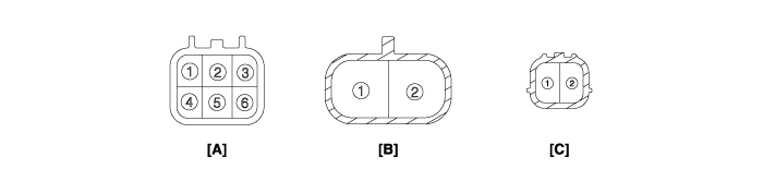
Connector Pin Function
| Connector | Pin No. | Function |
| A | 1 | 12V Power Ground |
| 2 | Climate CAN Low | |
| 3 | Interlock (-) | |
| 4 | 12V Power | |
| 5 | Climate CAN High | |
| 6 | Interlock (+) | |
| B | 1 | High Voltage Power |
| 2 | High Voltage Ground | |
| C | 1 | Compressor Interlock (-) |
| 2 | Compressor Interlock (+) |
Was this page helpful?