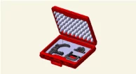
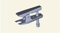
Non-reusable parts (Single-Use Parts) Workshop manual provides “Components and Components Location” which can be used to identify “Non-reusable parts”. When repairing a vehicle, Non-reusable parts such as fasteners, gaskets, washers, clips and garnishes must be replaced. Kia Non-reusable parts are designed to be installed only once. Before working on a vehicle, check “Components and Components Location” to find the non-reusable parts in a system. ※ Symbol of Non-reusable parts
Steering wheel does not return to its original position
Suspected Cause
Correction
Excessive turning resistance of tie rod end
Replacement
Yoke plug excessively tight
Adjustment
Faulty tie rod or ball joint
Replacement
Steering gear box and front sub frame got loose
Retighten
Steering column shaft or body grommet got worn
Repair or replace
Bended rack
Replacement
Rattling or chucking noise in the rack and pinion
Suspected Cause
Correction
Loose steering gear box mounting bolts
Retighten
Tie rod end ball joint got loose
Retighten
Tie rod or tie rod end ball joint got worn
Replacement
Loose yoke plug
Retighten
Inspection
Inspection
Steering Wheel Play Inspection
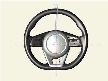
Align the steering wheel in a straight-ahead position using a digital level or other equivalent tools.
Allowable steering wheel alignment range : 0.0 ± 0.5°
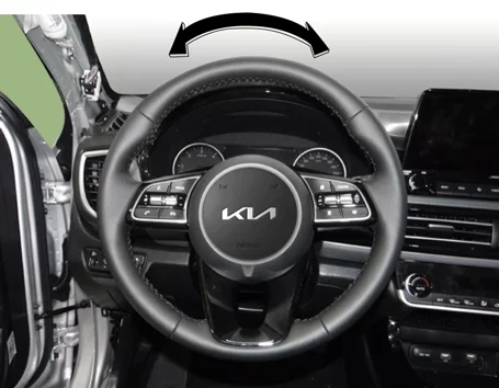
With MDPS power on, lightly turn the steering wheel from side to side to measure the distance the steering wheel rotates until the wheel moves.
Allowable steering wheel play : 0 - 30 mm ( 0 - 1.18 in.)
If the steering wheel play exceeds standard value, inspect the steering column, shaft, and linkages.
Align the steering wheel in a straight-ahead position using a digital level or other equivalent tools.
Allowable steering wheel alignment range : 0.0 ± 0.5°
With MDPS powered on, apply a spring scale to the end of the steering wheel and pull the scale to measure the force when the steering wheel begins to move.
Stationary steering force : Maximum 3.0 kgf (29.0 N, 6.6 lbf)
If the measured value exceeds standard value, inspect the steering gear box or MDPS.
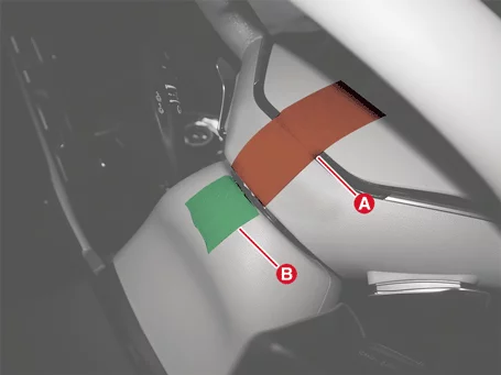
Mark the steering wheel upper (A) and upper cover (B) using the masking tape.
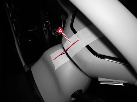
Align the steering wheel and mark the straight line (A) on the masking tape.
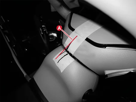
Keep the vehicle straight and drive about 100 m, and mark the new straight line (A) as the steering wheel is turned.
Remove the front wheel and tires. (Refer to Suspension System - "Wheel")
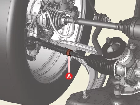
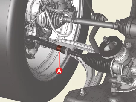
Loosen the tie rod end nut (A) enough to adjust the steering wheel off center. Tie rod tightening torque : 49.0 - 54 N·m
Fix the tie rod end (A) with a spanner to prevent turning during adjustment.
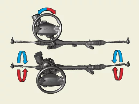
Turn the tie rod turnbuckle (A) clockwise or counterclockwise to adjust the steering wheel off center. [Tie rod turnbuckle rotation according to steering wheel off center]
During adjustment, check the distance (A) from time to time, do not adjust the turnbuckle in the direction of increasing the distance (A).
Adjust the RH and LH tie rods as below. (LH clockwise once → RH counterclockwise once)
Tighten the tie rod end nut (A) after adjustment. Tie rod tightening torque : 49.0 - 54 N·m
Install the front wheel and tires. (Refer to Suspension System - "Wheel")
Check the wheel alignment. (Refer to Suspension System - "Alignment")
Checking Stationary Steering Effort Steering Wheel Off Center Inspection