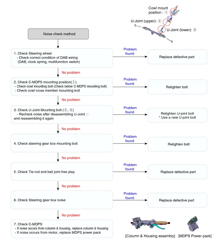
Noise / Malfunction Repairing Guide Check for abnormal noise
Symptoms
Possible causes and Inspection
Repair method
Abnormal noise
1. An abnormal noise from MDPS column and housing
–
Column & housing partial part exchange
– Check for the same noise after removing surrounding parts
–
Replace motor when checking motor noise
Abnormal noise
1. Check the handle and surrounding parts
Check the noise from the parts
– Check for DAB wiring harness and DAB, clock spring, multi-function switch
–
Check the parts
2. C - MDPS mounting check
Check the cowl for mounting condition
–
Remove the cowl mounting bolt, then reassemble it
(C-MDPS lower end fixing through-bolt included
3. Check the universal joint mounting bolt
If the bolt is worn, replace the universal joint mounting bolt
–
After removing and installing the universal joint completely, check the noise again.
4. check the column moves when steering while the vehicle is stopped
Secure clearance between parts
–
Check the main wiring connected to MDPS / Spacing between parts around shroud/ Check friction
–
Check the wiring and column for moves and clearance between parts
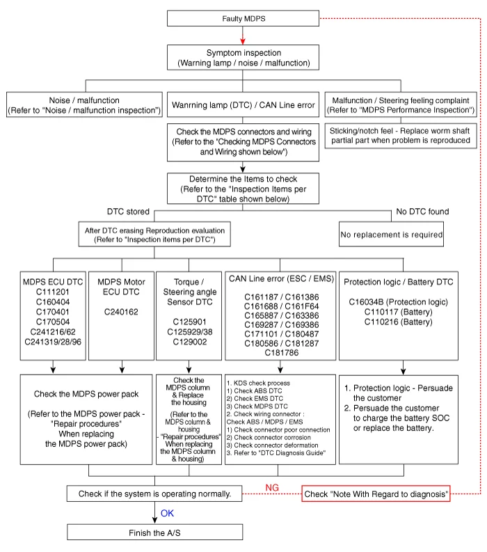
Repairing Guide for Warning Lights Inspection items by DTC code
DTC
Possible Cause
Inspection
Correction
C111201
Abnormal torque sensor power supply
Check the connector connection after erasing DTC
If DTC reoccurs, replace MDPS.
C11121C
Abnormal motor position sensor power supply
Check the connector connection after erasing DTC
If DTC reoccurs, replace MDPS.
C125901
Abnormal Steering Angle Sensor (SAS) signal
Erase DTC after performing 'Steering Angle Sensor(SAS) Calibration' Check the connector connection
If DTC reoccurs, replace MDPS column and housing.
C126154
Abnormal SAS signal
Erase DTC after performing 'Steering Angle Sensor(SAS) Calibration' Check the sensor connector connection
Perform 'Steering Angle Sensor(SAS) Calibration' or If DTC reoccurs, replace MDPS column and housing.
C129002
Abnormal torque sensor signal
Check after erasing DTC Check the sensor connector connection
If DTC reoccurs, replace MDPS column and housing.
C160404
ECU hardware error
Check after erasing DTC
If DTC reoccurs, replace MDPS.
C171101
ECU abnormal termination
Check after erasing DTC
If DTC reoccurs, replace MDPS.
C161386
Abnormal engine signal
1. Check chassis CAN connection / status 2. Check connectors mounting status 3. Check engine ECU 4. Check the engine stop history while driving
Erase DTC If DTC reoccurs, replace MDPS.
C161487
VCU6 CAN message not received
C161688
CAN communication circuit error
C161187
EMS CAN message not received
C162286
Abnormal vehicle speed signal
C162887
Cluster CAN message not received
Check cluster connector connection
C163386
Abnormal cluster vehicle speed signal
C169287
VSM CAN message not received
Check ESC, chassis CAN
C169386
Abnormal VSM signal
C170004
NVM check error
Check after erasing DTC
C170255
Tuning map data error
Check tuning map data
C170504
ECU pre-charge circuit error
Check after erasing DTC
C180287
VCU1 CAN message not received
Check CAN line
C180487
LKA CAN message not received
Check LKA, CAN line
C180586
Abnormal LKA signal
C180687
MCU CAN message not received
Check CAN line
C181287
Gateway CAN message not received
Check gateway
C181786
Abnormal P_STS signal
C240162
Abnormal motor position sensor
Check after erasing DTC
If DTC reoccurs, replace MDPS.
C241216
Open or shorted motor circuit
Check after erasing DTC
Replace MDPS
C241319
Motor current error
Check after erasing DTC
If DTC reoccurs, replace MDPS.
Cautions When Handling MDPS (Motor Driven Power Steering)
Internal damage may occur if parts fall, impact, or excessive load occurs. → If it is dropped or impacted, replace it with a new one.
Tightening the steering wheel with excessive force can distort the center of the torque sensor. → Tighten with specified torque.
Be careful not to apply excessive force as the wiring may be damaged by deformation when attaching/detaching the connector. → Do not use excessive connector insertion/removal.
Careful storage and replacement of partial parts under abnormal temperature and humidity conditions.
Adjustment
Diagnosis with KDS
System Identification (S/W Management → Motor Driven Power Steering → System Identification)
Refer to the KDS screen for operating conditions and details
Steering Angle Sensor(SAS) Calibration (S/W Management → Motor Driven Power Steering → Steering Angle Sensor(SAS) Calibration)
Refer to the KDS screen for operating conditions and details
EPS Type Recognition (S/W Management → Motor Driven Power Steering → EPS Type Recognition)
Refer to the KDS screen for operating conditions and details
MDPS Column & Housing On Vehicle Inspection
On Vehicle Inspection
the MDPS system can be more quickly diagnosed for problems with the KDS (Refer to "DTC guide").
Self Diagnosis : Inspect the Diagnostic Trouble Code (DTC) with the KDS (Refer to DTC guide when fault code is found)
S/W Management : Controlling other features including system option setting and zero point adjustment
Check the steering column for damage or deformation.
Check the universal joint for damage or wear.
Check the tilt bracket for damage or crack.
MDPS Column & Housing Removal and Installation
Removal
Align the steering wheel in a straight-ahead position using a digital level or other equivalent tools.
Allowable steering wheel alignment range : 0.0 ± 0.5°
Disconnect the battery negative ( - ) terminal.
Remove the steering wheel (Refer to Steering System - "Steering Wheel")
Remove the multifunction switch (Refer to Body Electrical System - "Multifunction Switch")
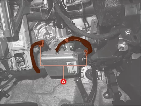
Disconnect the MDPS connectors (A).
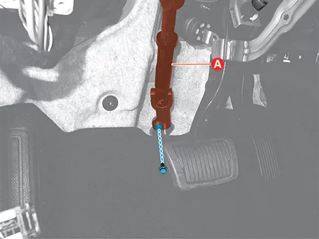
Remove the universal joint bolt (A), and separate the universal joint from the steering gear box.
Tightening torque : 49.0 - 59 N·m
Do not reuse the universal joint assembly bolt.
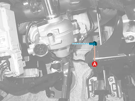
Remove the MDPS column & housing lower bolt (A).
Tightening torque : 53.9 - 59 N·m
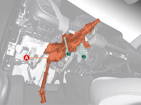
Remove the MDPS column & housing (A) after removing the upper nuts.
Tightening torque : 24.5 - 29 N·m
Installation
Install in reverse order of removal.
When installing a single unit, install it to the specified torque.
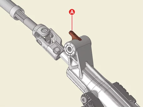
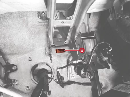
Ensure the dowel pin (A) into the MDPS bracket groove (B) when installing the steering column.
Tighten the steering gear joint by firmly inserting it into the steering gearbox pinion shaft during installation.
When installing, ensure that the universal joint assembly bolt head faces the driver.
Perform the 'EPS type recognition', 'Steering Angle Sensor(SAS) Calibration' by using KDS. (Refer to Motor Driven Power Steering (MDPS) - "Adjustment")
MDPS Column & Housing Disassembly and Reassembly
Disassembly
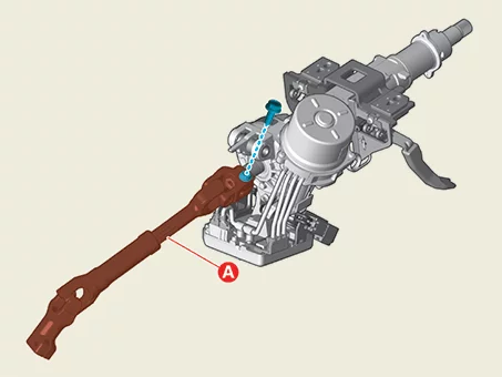
Remove the universal joint assembly (A) after removing the bolt.
Tightening torque : 49.0 - 52 N·m
Do not reuse the universal joint assembly bolt.
Reassembly
Reassemble in reverse order of disassembly.
Erase the DTC, and perform the "Steering Angle Sensor (SAS) calibration" by using the KDS. (Refer to Motor Driven Power Steering (MDPS) - "Adjustment")
Check the steering feel and abnormal noise to ensure it is operating normally.
Universal Joint Assembly On Vehicle Inspection
On Vehicle Inspection
Check the universal joint bearing for damage or wear.
Check whether the universal joint bolt is tightened.
Universal Joint Assembly Removal and Installation
Removal
Align the steering wheel in a straight-ahead position using a digital level or other equivalent tools.
Allowable steering wheel alignment range : 0.0 ± 0.5°
Disconnect the battery negative ( - ) terminal.
Fix the steering wheel by using a tool such as a steering wheel holder.
Changing the clockspring neutral position by rotating the steering wheel with the steering column universal joint removed may result in an open circuit and faulty folding of the cable inside the clockspring after installation.
Remove the driver side crash pad lower panel. (Refer to Body - "Crash Pad")
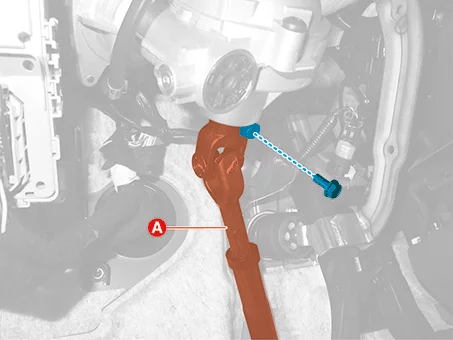
Remove the bolt, and then separate the universal joint (A) from the steering gear box.
Tightening torque : 49.0 - 59 N·m
Do not reuse the universal joint assembly bolt.
Remove the bolt, and then remove the universal joint assembly (A).
Tightening torque : 49.0 - 52 N·m
Installation
Install in reverse order of removal.
Insert the universal joint assembly securely into the steering gearbox pinion shaft.
When installing, ensure that the universal joint assembly bolt head faces the driver.
Perform the 'Steering Angle Sensor(SAS) Calibration' and 'Set the steering feel torque to zero'. (Refer to Motor Driven Power Steering (MDPS) - "Adjustment")
Steering Gear Box Removal and Installation
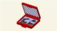
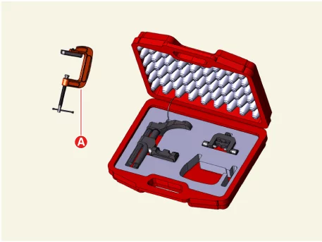
Special Service Tool
Tool Name / Number
Illustration
Description
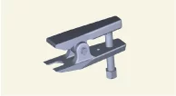
Ball joint puller 09568 - 1S100
Used for removal of tie rod end
Ball joint puller 0K545 - A9100
Used for removal of front lower arm ball joint
Removal
Align the steering wheel in a straight-ahead position using a digital level or other equivalent tools.
Allowable steering wheel alignment range : 0.0 ± 0.5°
Fix the steering wheel by using a tool such as a steering wheel holder.
Changing the clockspring neutral position by rotating the steering wheel with the steering column universal joint removed may result in an open circuit and faulty folding of the cable inside the clockspring after installation.
Remove the bolt, and then separate the universal joint (A) from the steering gear box.
Tightening torque : 49.0 - 59 N·m
Do not reuse the universal joint assembly bolt.
Remove the front wheel and tires. (Refer to Suspension System - "Wheel")
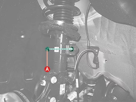
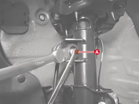
Separate the stabilizer bar link from the front strut assembly after removing the nut (A).
Tightening torque : 98.1 - 118 N·m
Fix the outer stud (A) using a tool such as a wrench when installing and removing the stabilizer bar link nut.
Be careful not to damage the boot of the link.
Use only a hand tool when removing or installing the stabilizer bar link nut.
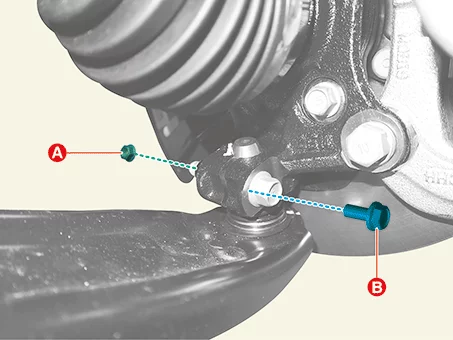
Separate the lower arm ball joint from the front axle.
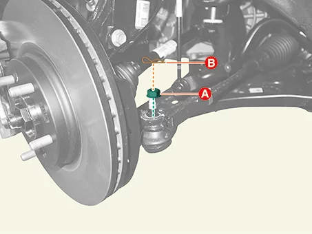
Remove the lower arm nut (A) and bolt (B).
Tightening torque : 58.8 - 71 N·m
Fix the lower arm ball joint bolt when removing or installing the nut.
Do not reuse the split pin.
Be careful not to change the bolt, nut and washer installing position.
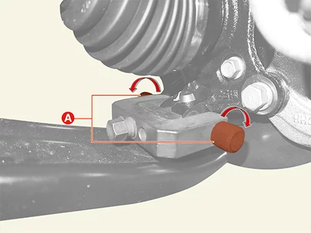
Install the support bolt to the lower arm ball joint mounting hole, and then rotate the bolts (A).
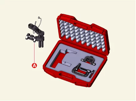
Use the support bolt (A) of SST (0K545 - A9100).
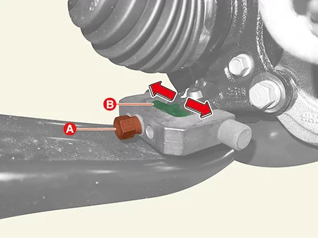
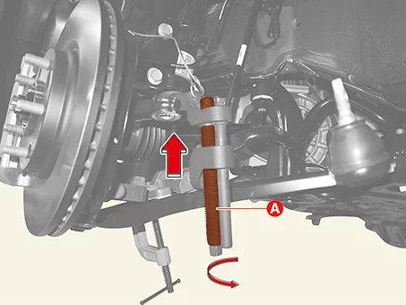
Place the support body (A) between the lower arm and the front axle (B).
Rotate the bolt (A) clockwise, and then insert the support body (B) to broaden the gap.
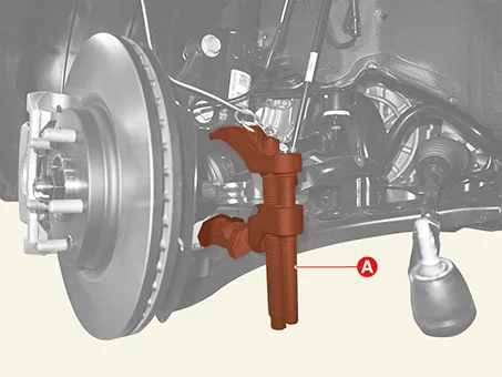
Install the main body (A) between the front strut assembly and front lower arm.
Use the main body (A) of SST (0K545 - A9100).
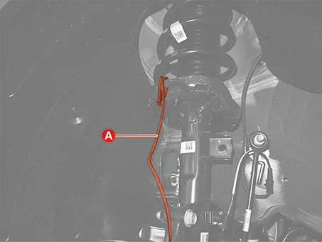
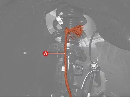
Secure the main body with the wire (A) to prevent it from falling.
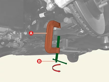
Install the C-clamp (A) by turning the handle (B) to prevent the main body from slipping.
Use the C-clamp (A) of SST (0K545 - A9100).
Tighten the bolt (A), and then separate the front lower arm from the front axle.
Separate the tie rod end ball joint from the front axle.
Remove the split pin (A).
Remove the lock nut (B).
Tightening torque : 34.3 - 44 N·m
Do not reuse the split pin.
Do not reuse the lock nut.
Be careful not to damage the boot of the link.
Use a hand tool when removing or installing the lock nut.
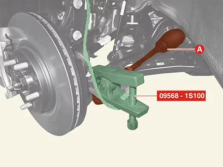
Separate the tie rod end ball joint (A) using the SST (09568 - 1S100).
Secure the SST (09568 - 1S100) to prevent it from falling off using the wire (A).
Remove the engine room rear under cover (A) after removing the nuts.
Tightening torque : 8.8 - 12,7 N·m
Remove the engine room under cover. G 1.6 MPI GAMMA (Refer to Engine Mechanical System - "Engine Room Under Cover") G 1.6 T-GDI GAMMA II (Refer to Engine Mechanical System - "Engine Room Under Cover") G 2.0 MPI NU (Refer to Engine Mechanical System - "Engine Room Under Cover")
Remove the bolt (A), and then separate the roll rod bracket from the roll rod support bracket.
Tightening torque : 107.9 - 128 N·m
Do not reuse the roll rod bracket bolt.
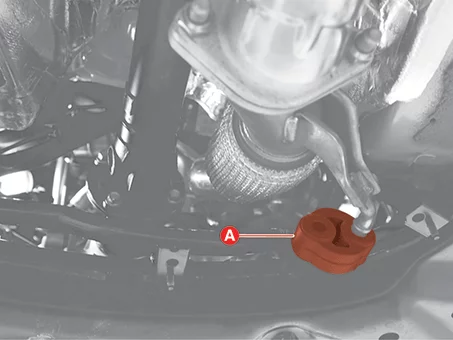
Remove the muffler rubber hanger (A) from the front sub frame.
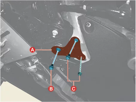
Remove the front sub frame stay (A). Tightening torque : (B) : 176.5 - 196 N·m (C) : 44.1 - 59 N·m [LH] [RH]
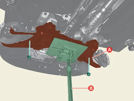
Support the front sub frame (A) with the jack (B) such as the transmission jack, and remove the front sub frame after removing the nut.
Tightening torque : 176.5 - 196 N·m
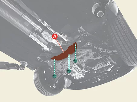
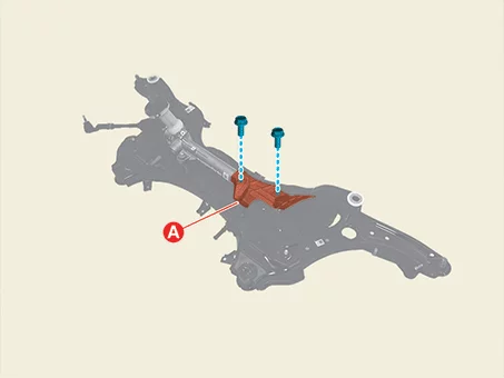
Remove the steering gear box heat protector (A) after removing the bolts.
Tightening torque : 7.8 - 11,8 N·m
Remove the steering gear box (A) after removing the bolts.
Tightening torque : 88.3 - 108 N·m
When installing the steering gear box, pre-tighten the bolts first before tightening in torque.
Installation
Install in reverse order of removal.
Check the alignment. (Refer to Suspension System - Alignment")
Perform the 'Steering Angle Sensor(SAS) Calibration' by using KDS. (Refer to Motor Driven Power Steering (MDPS) - "Adjustment")
Steering Gear Box Disassembly and Reassembly
Disassembly
Do not disassemble the steering gear box.
When replacing internal parts related to noise/cleanliness/functions other than simple fastening parts, the performance of part can not guarantee.
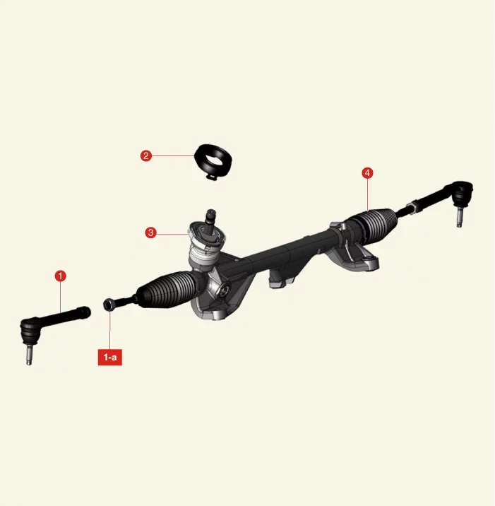
[Replaceable Parts]
1. Tie Rod End 1-a. 49.0 - 54 N·m
3. Dust Cap 4. Bellows
2. Dust Cap Packing
Bellows
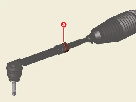
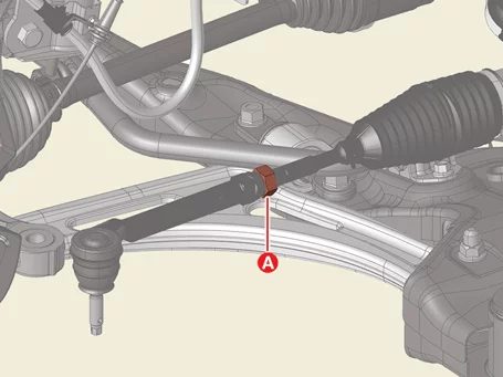
Loosen the tie rod end lock nut (A) until the tie rod end can rotate.
Rotate the tie rod end (A) counterclockwise to remove.
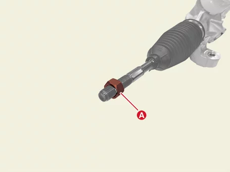
Remove the tie rod end lock nut (A).
Tightening torque : 49.0 - 54 N·m
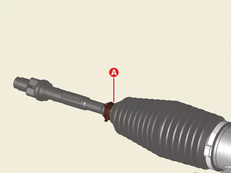
Remove the bellows clamp (A).
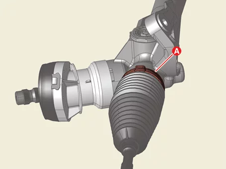
Remove the bellows band (A).
When assembling the bellows, install it with the band and then assemble.
Do not reuse the bellows band.
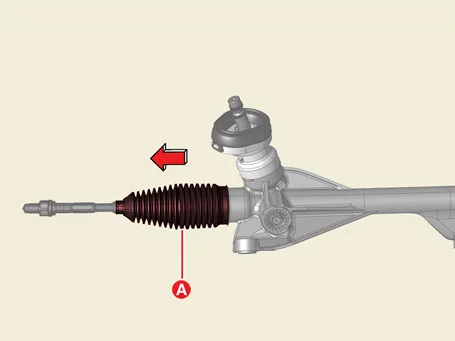
Remove the bellows (A) in the direction of the arrow.
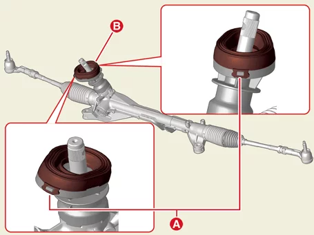
Release the mounting parts (A), and then remove the dust cap packing (B).
Remove the dust cap (A).
Dust cap
Reassembly
Bellows
Replace with a new bellows.
When assembling the bellows, install it with the band and then assemble.
Check the alignment. (Refer to Suspension System - "Alignment")
Replace with a new dust cap.
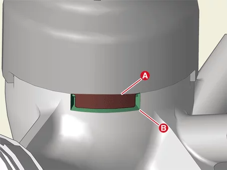
Ensure that the dust cap (A) fits into the steering gear box grooves (B) when assembling. [4 Points]
Clean the pinion shaft before reassembling.
Check the alignment. (Refer to Suspension System - "Alignment")
Dust cap
Tie Rod End Removal and Installation
Special Service Tool
Tool Name / Number
Illustration
Description
Ball joint puller 09568 - 1S100
Used for removal of tie rod end
Removal
Remove the front wheel and tires. (Refer to Suspension System - "Wheel")
Separate the tie rod end ball joint from the front axle.
Remove the split pin (A).
Remove the lock nut (B).
Tightening torque : 34.3 - 44 N·m
Do not reuse the split pin.
Do not reuse the lock nut.
Be careful not to damage the boot of the link.
Use a hand tool when removing or installing the lock nut.
Separate the tie rod end ball joint (A) using the SST (09568 - 1S100).
Secure the SST (09568 - 1S100) to prevent it from falling off using the wire (A).
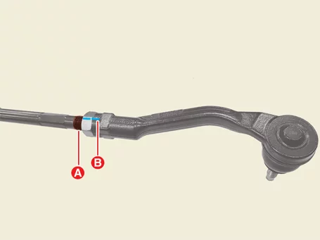
Loosen the tie rod end lock nut (A) until the tie rod end can rotate.
Tightening torque : 49.0 - 54 N·m
Measure the thread length (A) or mark the mounting position of the lock nut (B) before removing.
Rotate the tie rod end (A) counterclockwise to remove.
Installation
Install in reverse order of removal.
When installing a single unit, install it to the specified torque.
Replace the tie rod end with a new one.
Check the alignment. (Refer to Suspension System - "Alignment")