Engine Mechanical System
In this manual: Engine Mechanical System
11steps
~126min
5/5difficulty
12special tools
Done 0 of 11
Contents:
Single-Use Parts
Single-Use Parts
Non-reusable parts (Single-Use Parts) Workshop manual provides “Components and Components Location” which can be used to identify “Non-reusable parts”. When repairing a vehicle, Non-reusable parts such as fasteners, gaskets, washers, clips and garnishes must be replaced. Kia Non-reusable parts are designed to be installed only once. Before working on a vehicle, check “Components and Components Location” to find the non-reusable parts in a system. ※ Symbol of Non-reusable parts| Symbol | Meaning |
 |
Do not reuse the part. Replace with a new one. |
※ Example of “Components and Components Location”
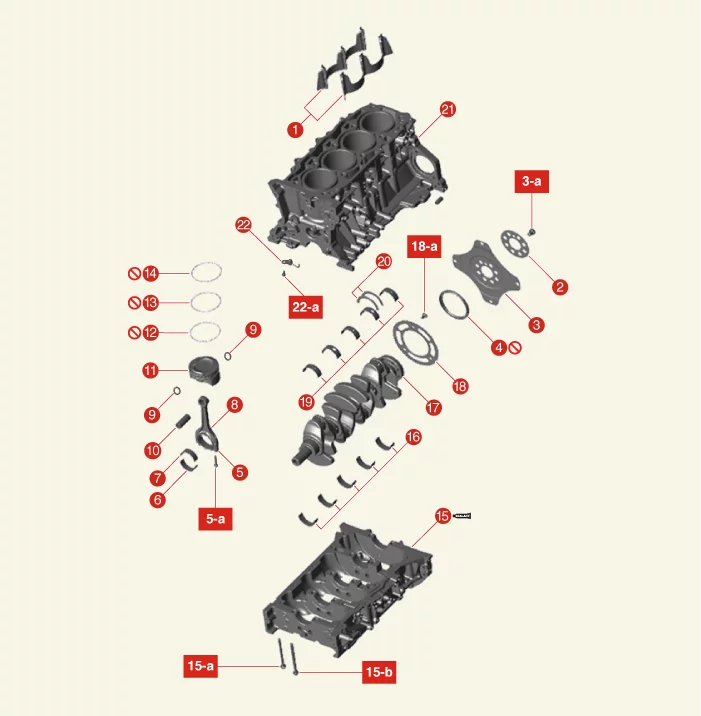
Specification ➤
Compression Pressure Inspection
Compression Pressure Inspection
|
- Start the engine, run it so that the coolant temperature is 80 - 95 °C, then stop.
- Remove the engine cover. (Refer to Engine and Transaxle Assembly - "Engine Cover")
- Disconnect the injector connector (A).
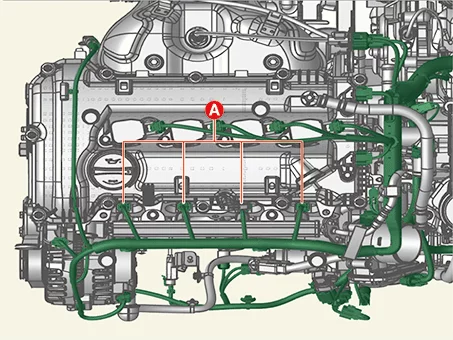
- Remove the ignition coil. (Refer to Engine Electrical System - "Ignition Coil")
- Remove the spark plug. (Refer to Engine Electrical System - "Spark Plug")
- Check the cylinder compression pressure.
- Insert a compression gauge into the spark plug hole.
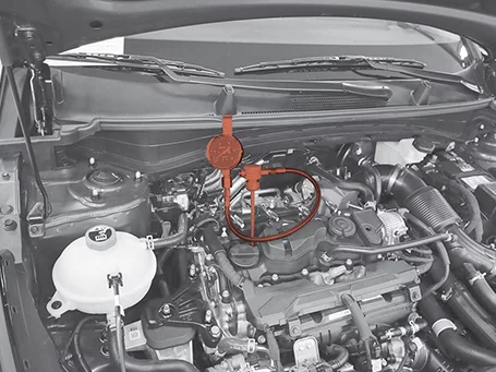
- Crank the engine over 20 times to measure compression pressure.
Always use a fully charged battery to obtain engine speed of 200 rpm or more.
- Repeat the process from (1) to (3) for each cylinder and measure.
This measurement must be taken in as short a time as possible.
Compression pressure Minimum pressure : 1,275 kPa (13.0 kgf/cm², 185 psi) Difference between each cylinder : 98 kPa (1.0 kg/cm², 14 psi) or less - If the compression pressure of the one or more cylinders is lower than the service limit, fill a small amount of engine oil through the cylinder ignition plug hole and repeat (1) to (3) for remeasurment.
- If the compression pressure rises due to the addition of engine oil, the piston ring or cylinder wall may have been worn and damaged.
- If the compression pressure does not rise, the valve may have worn out, the valve seat may not be in good contact, or gas may have leaked due to poor gasket.
- Insert a compression gauge into the spark plug hole.
- Install the spark plug. (Refer to Engine Electrical System - "Spark Plug")
- Install the ignition coil. (Refer to Engine Electrical System - "Ignition Coil")
- Install the injector connectors (A).
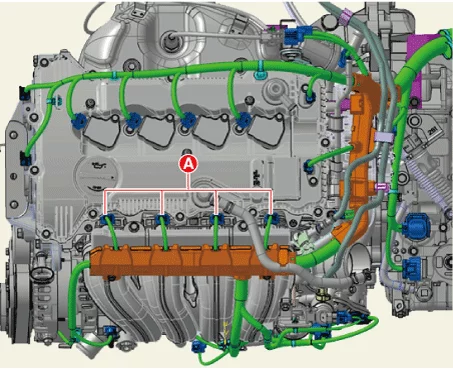
- After the above verification, some DTC codes may occur. In this case, the DTC code will be erased as KDS.
- Install the engine cover. (Refer to Engine and Transaxle Assembly - "Engine Cover")
Troubleshooting ➤
Special Service Tools
Special Service Tool
| Tool Name / Number | Illustration | Description |
| Crankshaft front oil seal installer 09231-2E000 |
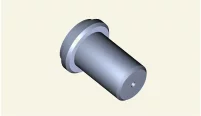 |
Used for installing crankshaft front oil seal |
| Valve stem seal installer 09222-2E000 |
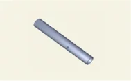 |
Used for installing valve stem seal |
| Valve spring compressor 09222-3K000 09222-3K100 |
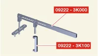 |
Used for removing installing intake or exhaust valve 09222-3K000 (Compressor) 09222-3K100 (Holder) |
| Crankshaft rear oil seal installer 09214-2E000 09231-H1100 |
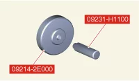 |
Used for installing crankshaft rear oil seal 09214-2E000 (Installer) 09231-H1100 (Handle) |
| Ring gear stopper 09231-2B100 09231-3N100 |
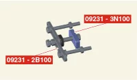 |
Used for removing / intalling crankshaft damper pulley |
| Ring gear stopper 09231-3D100 09231-2W100 |
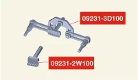 |
Used for removing / intalling crankshaft damper pulley |
| Oil pan remover 09215-3C000 |
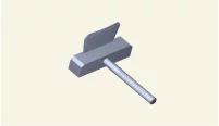 |
Removal of oil pan |
| Oil filter wrench 09263-2E000 |
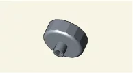 |
Used for removing and installing oil filter |
| Steel ball installer 0K221-2M100 |
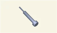 |
Used for installing steel ball |
| HLA air bleed tool 0K246 - L8000 |
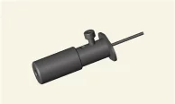 |
Used to air bleed HLA |
Cooling System ➤
Cylinder Block ➤
Cylinder Head Assembly ➤
Drive Belt System ➤
Engine and Transaxle Assembly ➤
Intake and Exhaust System ➤
Lubrication System ➤
Timing System ➤
Was this page helpful?