Fan
Components and Component Location
Components
[BLDC (Brushless DC) Motor Type]

| 1. Radiator 2. Cooling Fan Assembly |
3. Reservoir |
[DC Motor Type]

| 1. Cooling Fan 2. Cooling Fan Motor 3. Cooling Fan Shroud |
4. Cooling Fan Controller 5. Reservoir |
Description and Operation
Description
The cooling fan operates in 2 steps (HIGH/LOW). The Engine Control Module (ECM) controls the cooling fan based on coolant temperature, vehicle speed and air conditioning operation.
Specifications
Specification
[BLDC (Brushless DC) Motor Type]
| Items | Specification |
| Fan Type | Puller |
| Fan Speed Control Method | PWM |
| Air Flow Rate [m³/h (yd³/h)] | 3,500 (4,578) - 8% min. |
| Fan Speed (rpm) | 2 500 ± 8 % |
| Current (A) | 46.0 + 10% max. |
[DC Motor Type]
| Items | Specification |
| Fan Type | Puller |
| Fan Speed Control Method | PWM |
| Air Flow Rate [m³/h (yd³/h)] | 2,600 (3,401) - 8% min. |
| Fan Speed (rpm) | 2000 ± 8 % |
| Current (A) | 23.3 + 10% max. |
Circuit Diagrams
Wiring Diagram
[BLDC (Brushless DC) Motor Type]

[DC Motor Type]

Repair Procedures
Removal and Installation
Cooling Fan Assembly
Disconnect the negative battery cable.
Remove the front brace (A).
[RH]

[LH]

Remove the reservoir tank.
(See Cooling System - Reservoir Tank)
Disconnect the cooling fan connector (A).
[BLDC (Brushless DC) Motor Type]

[DC Motor Type]

Remove the front bumper assembly.
(Refer to Body (Interior and Exterior) - "Front Bumper Assembly")
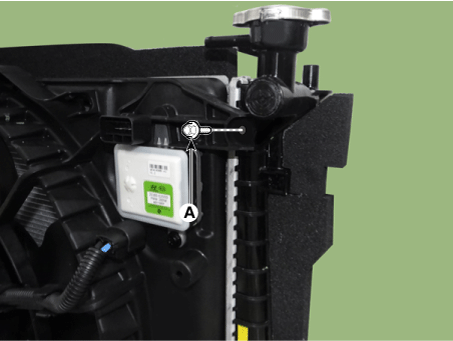
Remove the cooling fan assembly mounting bolts (A).
Tightening torque:
4.9–7.8 N·m (0.5–0.8 kgf·m, 3.6–5.8 ft·lbf, 43.4–69.4 in·lbf)

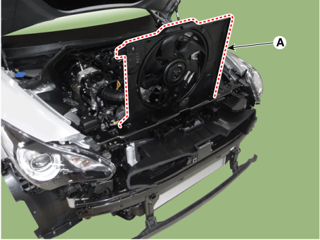
Remove the cooling fan assembly (A).
Install the remaining parts in the reverse order of removal.
Cooling Fan Controller (PWM) [DC Motor Type Only]
Disconnect the negative battery cable.
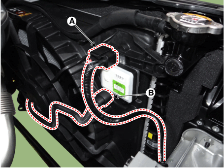
Disconnect the cooling fan controller (PWM) connector (A) and the cooling fan motor connector (B).
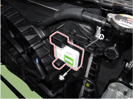
Remove the cooling fan controller (PWM) (A).
Tightening torque:
4.9–8.3 N·m (0.50–0.85 kgf·m, 3.6–6.1 ft·lbf, 43.4–73.8 in·lbf)
Install the remaining parts in the reverse order of removal.
Disassembly
[DC Motor Type Only]
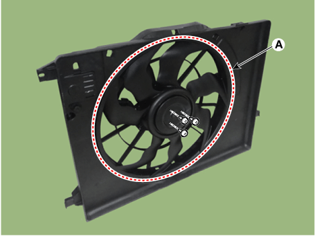
Remove the cooling fan (A) from the cooling fan assembly.
Tightening torque:
2.8–3.2 N·m (0.28–0.33 kgf·m, 2.03–2.39 ft·lbf, 24.3–28.6 in·lbf)
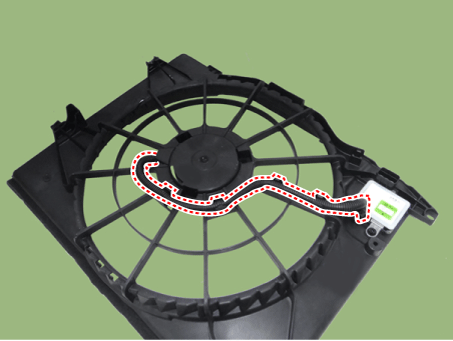
Disconnect the cooling fan motor connector (A).
Remove the fan motor (A) from the cooling fan shroud.
Tightening torque:
3.9–5.9 N·m (0.4–0.6 kgf·m, 2.9–4.3 ft·lbf, 34.7–52.1 in·lbf)
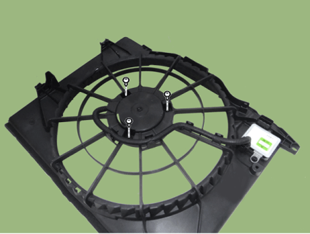
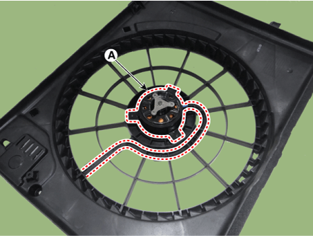
Installation is in the reverse order of removal.
Inspection
Blower motor
Disconnect the fan motor connector from the resistor.
Connect battery voltage to the "+" terminal and ground to the "-" terminal.
Check that the cooling fan motor operates properly.
Test yourself
A quick Kia Stinger CK quiz: every answer comes with an explanation and a link to the manual page.