CVVT and Camshaft
Description and Operation
Description
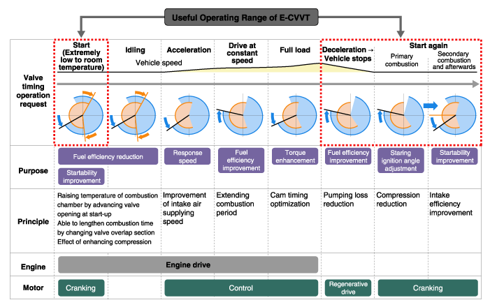
The E-CVVT system is an electric continuously variable valve timing system. It is located on the engine intake camshaft and uses engine rotation to control the camshaft angle relative to crankshaft rotation, independent of engine oil pressure. E-CVVT controls the DC motor current (duty signal) to control the system more precisely than the previous hydraulic type, increasing camshaft response speed to improve starting performance and reduce exhaust emissions. The intake valve operating range (valve opening angle) is also expanded. Therefore, power and fuel economy are improved.
Operation
Repair Procedures
Removal
Remove the timing chain.
(Refer to Timing System - Timing Chain Drive)
Remove the cylinder head cover.
(Refer to Cylinder Head Assembly - "Cylinder Head Cover")
Remove the fuel pump bracket (A).
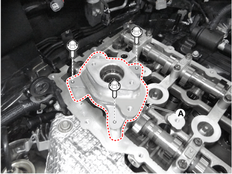
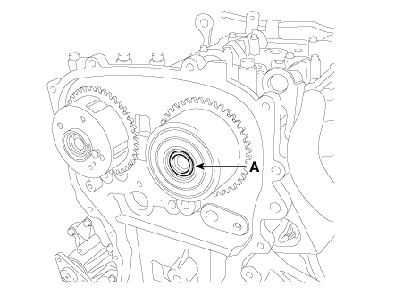
Remove it by breaking the center of the E-CVVT engine connector (A).
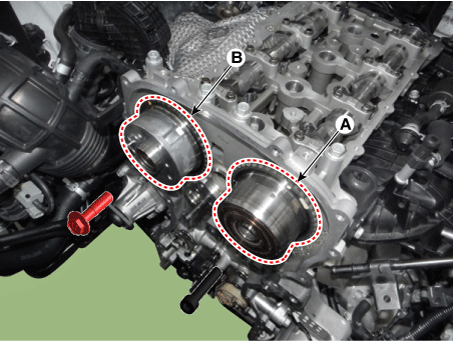
Disconnect the E-CVVT intake unit (A) and the CVVT exhaust unit (B).

Remove the camshaft.
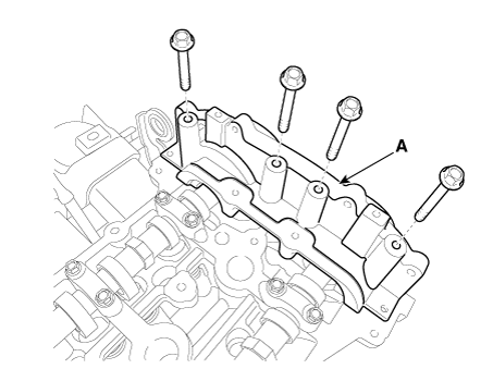
Remove the front camshaft bearing cap (A) with the upper bearing.
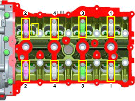
Remove the camshaft bearing caps in the specified sequence.
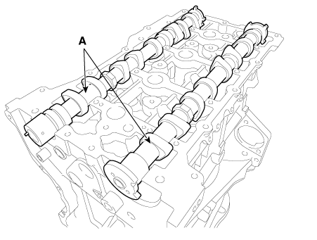
Remove the camshafts (A).
Remove the exhaust camshaft lower bearing cap (A).

Inspection
CVVT Assembly
Inspect the CVVT for smooth rotation.
Clamp the camshaft in a vise. Be careful not to damage the cam lobes and journals in the vise.
Make sure the CVVT is locked by turning it clockwise or counterclockwise. It should not rotate.
Exhaust CVVT: Seal one of the two holes in the camshaft journal with tape.
[Exhaust]
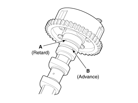
Exhaust CVVT: Apply approx. 150 kPa (1.5 kgf/cm², 21 psi) compressed air to the unsealed retard hole to release the lock.
Exhaust CVVT: While applying compressed air, turn the CVVT in the retard direction (clockwise), and make sure the CVVT rotates smoothly.
CVVT phase range
Exhaust: 22.5°±1° (from the most advanced position to the most retarded position)
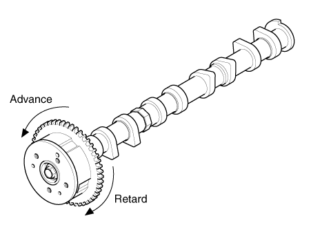
Exhaust CVVT: Turn the CVVT to the most advanced position (counterclockwise), then make sure the CVVT is locked.
Camshaft
Inspect the cams.
Using a micrometer, measure the cam lobe height.
Cam Lobe Height
[Standard Value]
Intake: 44.10–44.30 mm (1.7362–1.7440 in)
Exhaust: 44.90–45.10 mm (1.7677–1.7756 in)

If the cam lobe height is less than the standard value, replace the camshaft.
Inspect the camshaft journal oil clearance.
Clean the camshaft bearing caps and journals.
Install the camshafts on the cylinder head.
Place a strip of Plastigage on each camshaft journal.

Install the bearing caps.
Remove the bearing caps.
Measure the Plastigage at its widest point.
Bearing Oil Clearance
[Standard Value]
Intake:
No. 1: 0.029–0.057 mm (0.00114–0.00224 in)
No. 2, 3, 4, 5: 0.037–0.067 mm (0.00146–0.00264 in)
Exhaust:
No. 1: 0.004–0.036 mm (0.00016–0.00142 in)
No. 2, 3, 4, 5: 0.037–0.067 mm (0.00146–0.00264 in)

If the oil clearance is greater than the maximum, replace the camshaft. If necessary, replace the cylinder head.
Completely remove the plastigage.
Remove the camshafts.
Inspect the camshaft end play.
Install the camshafts.
Using a dial indicator, measure the camshaft end play by moving the camshaft back and forth.
Camshaft End Play
[Standard Value]: 0.04–0.16 mm (0.0016–0.0063 in)

If the end play exceeds the limit, replace the camshaft. If necessary, replace the cylinder head.
Remove the camshafts.
Installation
Install the exhaust camshaft lower bearing (A).
Install the camshafts (A).
Install the upper bearing (A) of the exhaust camshaft onto the front camshaft bearing cap.
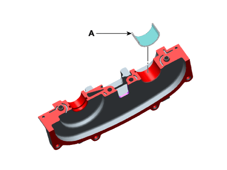
Install the camshaft bearing caps.
Using a gasket scraper, remove all old gasket material from the sealing surfaces.
The sealant application areas on the cylinder head and mating parts (front camshaft bearing cap) must be free of harmful foreign material, oil, dust and moisture. Spray cleaner onto the surface and wipe with a clean rag.
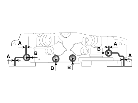
Before installing the front camshaft bearing cap, apply liquid gasket to the cylinder head surfaces.
Assemble the part within 5 minutes after applying the sealant.
Side Panel Width
Section A: 2.0–3.0 mm (0.08–0.12 in)
Section B: 1.5–2.5 mm (0.06–0.10 in)
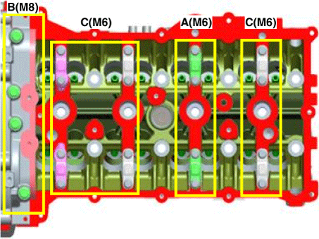
Install the camshaft bearing caps (A) in their original positions.
Tightening Sequence
Group A → Group B → Group C.
Tightening torque:
Step 1
M6: 5.9 N·m
M8: 14.7 N·m
Step 2
M6: 10,8–12.7 N·m
M8: 27,5–31 N·m
Install the E-CVVT intake unit (A) and the CVVT exhaust unit (B).
Tightening torque:
E-CVVT Intake Assembly
73,5–83 N·m
CVVT Exhaust Assembly
53,9–64 N·m
Install the fuel pump bracket (A).
Tightening torque: 18.6 – 24 N·m
Install the cylinder head cover.
(Refer to Cylinder Head Assembly - "Cylinder Head Cover")
Install the timing chain cover.
(See Valve Timing - "Timing Chain Cover")
Clean the mounting surface of the E-CVVT engine plug (A) using oil cleaner.

When reusing the E-CVVT cover, inspect the following items.
If there are signs of leakage inside the E-CVVT cover, replace it with a new one.
Check whether the connecting brush is worn.
Specification: More than 5 mm (0.1969 in.)

If the dimension is below specification, replace the E-CVVT cover with a new one.
Check the oil seal (A) for damage and replace the damaged E-CVVT cover with a new one.

After inspecting the E-CVVT, if no problems are found, replace the O-ring (A) with a new one.

Install the E-CVVT cover.
Apply engine oil to the lip of the oil seal (A).

Insert the SST (09243-C2000) into the E-CVVT engine shaft.
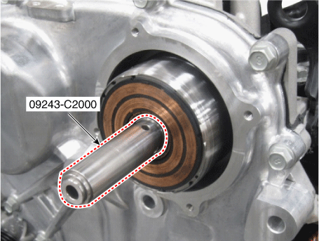
Slowly press the E-CVVT cover (A) until it is flush with the timing chain cover surface.

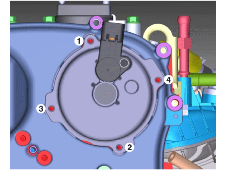
Pre-tighten the bolts in the sequence shown below, then remove the SST (09243-C2000).
Tightening torque:
1.0–2 N·m (0.1–0.2 kgf·m, 0.7–1.4 ft-lbf, 8.7–17.4 in-lbf)

Tighten the bolts to the specified torque in the sequence shown below.
Tightening Torque: 9.8–11.8 N·m
Install the E-CVVT plug.
Using the SST (09243-C2000), insert the plug (A) into the E-CVVT cover hole.
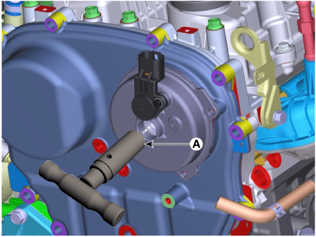
Install the SST stopper so that it is located at the end of the E-CVVT engine shaft.

Check the press-in depth of the E-CVVT plug.
Using a steel rule, measure the distance from the E-CVVT cover boss center to the end of the engine shaft (①).
Using a steel rule, measure the distance from the E-CVVT cover center boss to the end of the E-CVVT plug (②).

Calculate the press-in depth (③) of the engine plunger.
If it does not meet the specification, replace the E-CVVT plug with a new one and reinstall it.
Press-in depth: ③ = ② - ① Specification: 1.9–2.1 mm (0.0748–0.0827 in.)
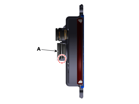
Install the E-CVVT cover plug so that the protrusion (A) correctly engages the E-CVVT cover groove.
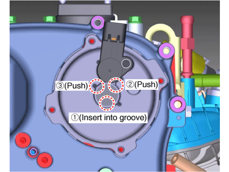
Install the remaining parts in the reverse order of removal.
Test yourself
A quick Kia Stinger CK quiz: every answer comes with an explanation and a link to the manual page.