Heater Control Unit
Description and Operation
Description
Smart Ventilation
This system actively ventilates when the humidity inside the passenger compartment increases with the A/C switched off.
Entry Conditions
a. A/C OFF
b. When humidity rises
b. Vehicle speed 25 km/h or more
d. Intelligent ventilation system setting ON
Release conditions
a. A/C ON
b. AVN setting OFF
b. Vehicle speed less than 15 km/h
d. Intelligent ventilation system setting OFF
Operating characteristics
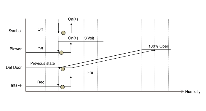
When humidity inside the compartment increases, the following systems will be activated in the following order.
a. Switching REC → FRE and illumination of the symbol ("INTELLIGENT VENTILATION ON")
b. The defrost door inside the heater gradually opens according to the increase in humidity in the compartment.
b. Blower activated. (Operates at 3.0 V)
Components and Component Location
Components
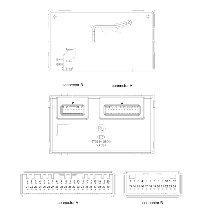
Connector Terminal Function
[Connector A]
| Pin No. | Function | Pin No. | Function |
| 1 | Mode control actuator (F/B) | 21 | Mode control actuator (VENT) |
| 2 | Intake Actuator (F/B) | 22 | Mode control actuator (DEF) |
| 3 | Passenger temperature control actuator (F/B) | 23 | Intake Actuator (FRE) |
| 4 | Driver temperature control actuator (F/B) | 24 | Intake Actuator (REC) |
| 5 | Automatic anti-fog actuator (F/B) | 25 | Passenger temperature control actuator (COOL) |
| 6 | - | 26 | Passenger temperature control actuator (WARM) |
| 7 | Vehicle sensor (+) | 27 | Driver temperature control actuator (COOL) |
| 8 | Left photo sensor (-) | 28 | Driver temperature control actuator (WARM) |
| 9 | Right photo sensor (-) | 29 | Automatic Anti-Fog Actuator (OPEN) |
| 10 | Console temperature control actuator (F/B) | 30 | Automatic Anti-Fog Actuator (CLOSED) |
| 11 | Console ON/OFF actuator (F/B) | 31 | - |
| 12 | Console switch (F/B) | 32 | - |
| 13 | Automatic anti-fog signal | 33 | - |
| 14 | Ambient Temperature Sensor (+) | 34 | P may be LOW |
| 15 | Evaporator Temperature Sensor (+) | 35 | P may be HIGH |
| 16 | - | 36 | - |
| 17 | Console temperature control actuator (COOL) | 37 | - |
| 18 | Console temperature control actuator (WARM) | 38 | - |
| 19 | Console ON/OFF actuator (OPEN) | 39 | - |
| 20 | Console ON/OFF actuator (CLOSED) | 40 | Ground |
[Connector B]
| Pin No. | Function | Pin No. | Function |
| 1 | Ground | 13 | Ground |
| 2 | Sensor Ground | 14 | ECV (-) |
| 3 | PT (GATE) | 15 | ECV (+) |
| 4 | Field effect transistor drain (F/B) | 16 | - |
| 5 | Blower Motor (+) | 17 | - |
| 6 | - | 18 | PTC ON Signal |
| 7 | - | 19 | PTC Relay 2 |
| 8 | - | 20 | PTC Relay 3 |
| 9 | REF sensor (5V) | 21 | - |
| 10 | - | 22 | LIN BUS |
| 11 | - | 23 | IGN1 |
| 12 | Battery (+) | 24 | IGN2 |
Repair Procedures
Replacement
Disconnect the negative (-) battery terminal.
Remove the glove box housing.
(Refer to Body - "Glove Box Housing")
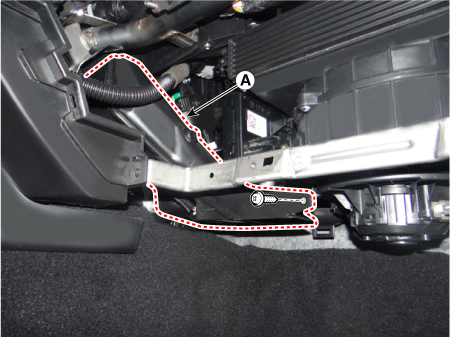
Remove the shower duct (A) after loosening the screw.
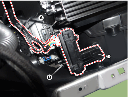
Disconnect the heater control unit connectors (A).
Remove the heater control unit (B) after loosening the screws.
Install in the reverse order of removal.
Test yourself
A quick Kia Stinger CK quiz: every answer comes with an explanation and a link to the manual page.