Dual Automatic Temperature Control (DATC) Unit
Components and Component Location
Components

Connector Terminal Function
Connector A
| Pin No. | Function | Pin No. | Function |
| 1 | Battery (+) | 13 | IGN2 |
| 2 | ILL (+) | 14 | ISG Power |
| 3 | - | 15 | IGN1 |
| 4 | - | 16 | - |
| 5 | LIN BUS | 17 | - |
| 6 | - | 18 | - |
| 7 | HTD | 19 | - |
| 8 | - | 20 | - |
| 9 | Rear Heater Switch | 21 | - |
| 10 | - | 22 | HOLD (-) |
| 11 | - | 23 | - |
| 12 | BATT (-) | 24 | Ground |
Repair Procedures
Self-Diagnosis
Self-Diagnosis Procedure
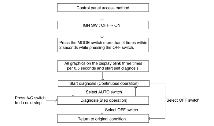
How to Read the Self-Diagnosis Code
After the display panel flashes three times at 0.5-second intervals, the corresponding fault code flashes on the set temperature display at 0.5-second intervals and a two-digit number is shown. The codes are indicated in numeric format.
Trouble Code Display
Continuous operation: one DTC

Continuous operation: more than two DTCs.

STEP Operation
A. Normal or one fault code matches continuous operation.
B. More than two DTCs.

If trouble codes are displayed during inspection, check the possible causes of the malfunction by referring to the trouble codes.
Display Description of Malfunction 0 Normal 11 In-Car Sensor Open 12 In-Car Sensor Short Circuit 13 Ambient Sensor Open 14 Ambient Air Sensor Short Circuit 17 Evaporator Sensor Open 18 Evaporator Sensor Short Circuit 19 Air Temperature Door Potentiometer Open/Short - Actuator 20 Air Temperature Door Potentiometer Malfunction - Actuator 21 Mode Door Potentiometer Open/Short 22 Mode Door Potentiometer Malfunction 23 Anti-Fog Sensor Open 24 Anti-Fog Sensor Short Circuit 25 Intake Door Potentiometer Open/Short Circuit 26 Intake Door Potentiometer Malfunction 32 Air Temperature Door Potentiometer Open/Short - Passenger 33 Air Temperature Door Potentiometer Malfunction - Passenger 34 Console Temperature Door Potentiometer Open/Short Circuit 35 Console Temporary Door Potentiometer Malfunction 36 Console ON/OFF Door Potentiometer Open/Short 37 Console ON/OFF Door Potentiometer Malfunction 43 Anti-Fog Potentiometer Open/Short Circuit 44 Auto Defog Potentiometer Malfunction 45 APT CAN signal error 47 RPM CAN Signal Malfunction 48 Vehicle Speed CAN Signal Malfunction 49 Engine Coolant Temperature CAN Signal Malfunction 66 Console Temperature Switch Open/Short 71 Electronic Control Valve Malfunction 72 Panel LIN Communication Error Fail-safe
NO. Item Fault Fail-safe 1 Vehicle Sensor Open or short Monitor value 25 °C 2 Ambient Temperature Sensor Open or short Monitor value 20 °C 3 Evaporator Temperature Sensor Open or short Monitor value -2°C (28.4°F) 4 TEMPERATURE DOOR POTENTIOMETER Open or short If the set temperature is 17°C-24.5 °C, fix the position to maximum cooling. If the set temperature is 25°C-32°C, fix the position to maximum heating. 5 MODE DOOR POTENTIOMETER Open or short Fix the position to ventilation in ventilation mode. Fix the position to defrost in all modes except ventilation mode. 6 INTAKE DOOR POTENTIOMETER Open or short Fix the fresh air position in fresh air mode. Fix the recirculation position in recirculation mode. 7 DEFOG DOOR POTENTIOMETER Open or short Fix the closed position when the closed mode is selected. Fix the open position in other cases. 8 ECV Open CF_Fatc_EcvFlt = 01H (malfunction) ECV OFF, A/C output OFF, torque 0.2 N·m 9 NOTICE Open or short HUMIDITY 0% 11 C_SunRoofOpenState NO request Check until "CLOSE" value 17 F_N_ENG NO request 650 rpm 18 N F_N_ENG="Error" or NO request 650 rpm 20 RLI _ AC NO request Compressor OFF (ECV OFF) 21 VS (Vehicle Speed) FFh or no reception VS-TCU (from TCU2) 22 VS TCU (vehicle speed calculated by TCU) FFh or no reception Monitor value 0 km/h 27 PV_AV_CAN FFh or no reception Actuator control with 0% value 28 TEMP_ENG FFh or no reception 90°C 29 R _ PAcnC (APT sensor output value) FFh or no reception Control with 0 hPa value (ECV OFF) 32 R_TqAcnApvC FFh or no reception Control with 0 N·m value
Replacement
Disconnect the negative (-) battery terminal.
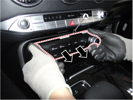
Remove the heater and A/C control unit (A).
Disconnect the connectors (A) from the heater and A/C control unit.

Install in the reverse order of removal.
Test yourself
A quick Kia Stinger CK quiz: every answer comes with an explanation and a link to the manual page.