Temperature Control Actuator
Description and Operation
Description
The heater unit consists of the mode control actuator and the temperature control actuator.
The temperature control actuator located in the heater unit adjusts the temperature in the following procedures.
The signal from the control unit adjusts the position of the temperature door by controlling the temperature actuator. The temperature is then regulated by the hot/cold air ratio determined by the position of the temperature door.
Repair Procedures
Inspection
Turn the ignition off.
Disconnect the temperature control actuator connector.
Check that the temperature control actuator moves to the cool position when 12 V is connected to terminal 3 and ground is connected to terminal 7.
Check that the temperature control actuator operates in the warm position when the connections are reversed.
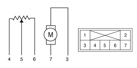
1. -
2. -
3. Warm position
4. Sensor ground5. Feedback signal
6. Sensor (+5V)
7. Cool positionConnect the temperature control actuator connector.
Turn the ignition on.
Check the voltage between terminals 5 and 4.
Specification
Door Position Voltage (V) Fault Detection Max. cool (driver side) 0.3 ± 0.15 V Low voltage: 0.1 V or less
High voltage: 4.9 V or moreMax. warm (driver side) 4.7 ± 0.15 V Max. Cool (Passenger Side) 0.3 ± 0.15 V Max. Heat (Passenger Side) 4.7 ± 0.15 V
The current actuator position will be sent to the control unit.
If the measured voltage is not within specification, replace the temperature control actuator with a known good one and verify proper operation.
Replace the temperature control actuator if it is determined to be the cause of the problem.
Replacement
[Driver's Side]
Disconnect the negative (-) battery terminal.
Remove the knee airbag.
(See Restraint System - "Knee Airbag (KAB) Module").
Disconnect the connector (A), then remove the temperature control actuator (B) after loosening the mounting screws.
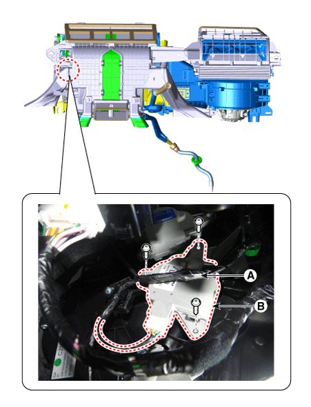
Install in the reverse order of removal.
[Passenger Side]
Disconnect the negative (-) battery terminal.
Remove the glove box housing.
(Refer to Body - "Glove Box Housing")
Remove the passenger side cabin duct (A) after loosening the screw.
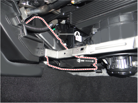
Disconnect the connector (A) and remove the temperature control actuator (B) after loosening the screws.
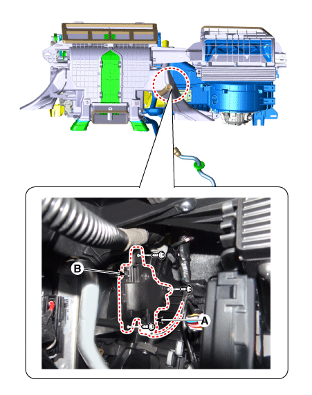
Install in the reverse order of removal.
Test yourself
A quick Kia Stinger CK quiz: every answer comes with an explanation and a link to the manual page.