Engine Room Junction Block
Components and Component Location
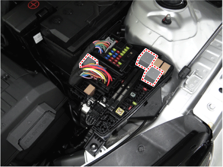
Component Location
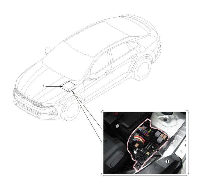
| 1. Engine Room Junction Block |
Repair Procedures
Inspection
Power Relay (Type A)
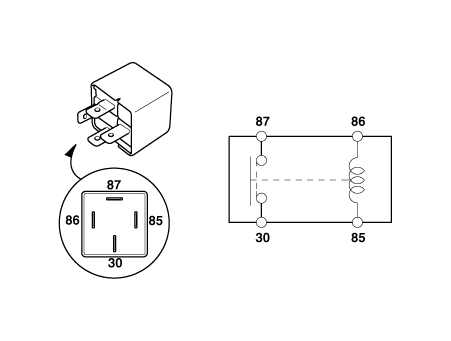
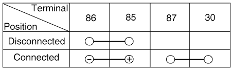
Check the circuit between the terminals for continuity.
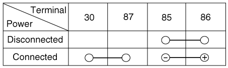
After applying power between relay terminals No. 85 and 86, check that continuity exists between terminals No. 30 and 87.
With power removed from power relay terminals No. 85 and 86, check that there is no continuity between terminals No. 30 and 87.
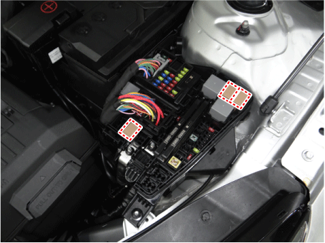
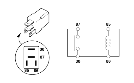
Power Relay (Type B)
Check the circuit between the terminals for continuity.
After applying power between relay terminals No. 85 and 86, check that continuity exists between terminals No. 30 and 87.
With power removed from power relay terminals No. 85 and 86, check that there is no continuity between terminals No. 30 and 87.
Fuse
Make sure the fuse holders are secured firmly and the fuses are securely held in place by the holders.
Make sure that each fuse circuit has the correct fuse rating.
Inspect the fuses for damage.
Multi Fuse
Disconnect the negative battery cable.
Loosen the multi-fuse mounting nut (A).
Remove the multi-fuse (B) by releasing the hook.
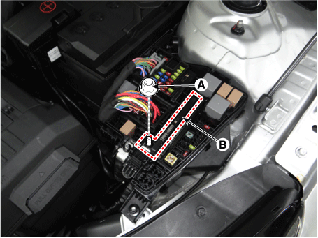
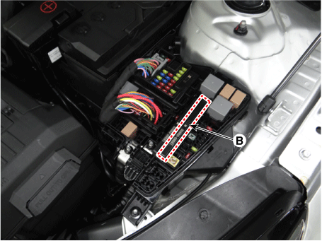
Inspect the multi-fuses for damage.
Removal
Engine Room Printed Circuit Board Unit
Disconnect the negative battery cable.
Disconnect the connector (A).
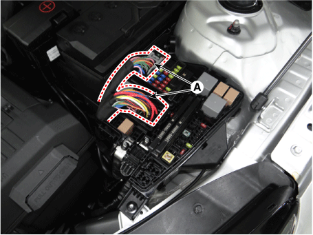
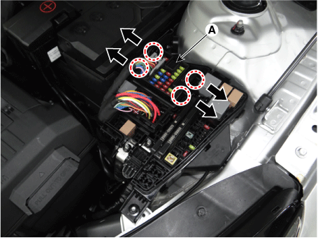
Press the hooks in the direction of the arrow and lift the engine room printed circuit board unit (A).
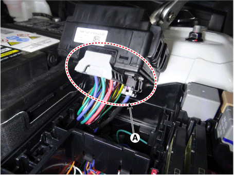
Disconnect the connectors (A) from the engine room printed circuit board unit.
Installation
Install in the reverse order of removal.
Test yourself
A quick Kia Optima DL3 quiz: every answer comes with an explanation and a link to the manual page.