Fuel pump module
Specifications
Specification
| Items | Specification | |
| Current (A) | Max. 6.0 | |
| Supply Voltage (V) | 12 | |
| Fuel Pressure | bar | 3,3 - 3,7 |
| kPa | 330 - 370 | |
| kgf/cm² | 3,365 - 3,772 | |
| psi | 47,86 - 53,66 | |
Fuel Sender
| Position | Resistance (Ω) | Capacity (L) |
| E | 297 - 305 | 2 |
| 1/2 | 80 - 84 | 30,7 |
| F | 14 - 16 | 58,3 |
Components and Component Location
Component
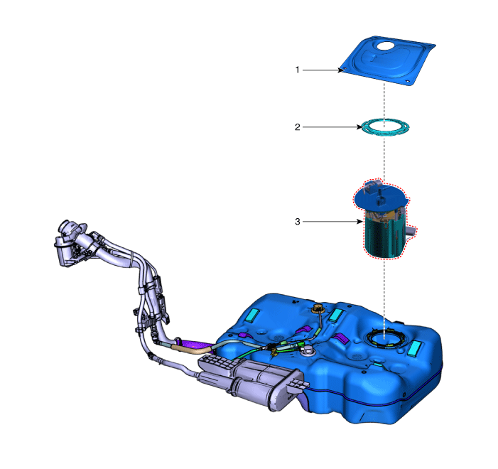
| 1. Service Cover 2. Plate Cover |
3. Fuel Pump Module |
Repair Procedures
Inspection
The fuel system can be diagnosed more quickly for malfunctions using the Kia Diagnostic System (KDS). (Refer to the Trouble Code Manual.)
KDS provides the following information.
Self-diagnosis: Checks and displays diagnostic trouble codes (DTC).
Data list: Checks the input/output values of the system.
Active test: Checks the operating condition of the system.
Additional functions: System option control, zero point adjustment, and other functions.
Component Inspection
Fuel pump
Disconnect the negative battery cable.
Remove the fuel pump module.
Check fuel pump operation by connecting the fuel pump connector (A) to power (4) and ground (5).
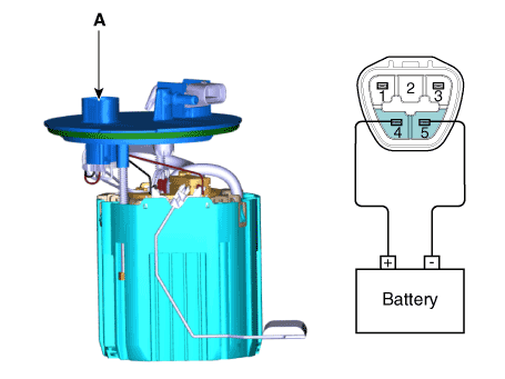
Pin Description 1 Fuel sensor signal (+) 2 - 3 Fuel sensor ground (-) 4 Fuel pump (+) 5 Fuel Pump (-)
Fuel Sender
Disconnect the negative (-) battery terminal.
Remove the fuel pump assembly.
Using an ohmmeter, measure the resistance between terminals 1 and 3 of the sensor connector (A) at each float level.
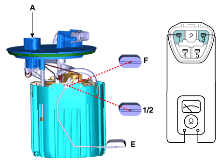
Pin Description 1 Fuel sensor signal (+) 2 - 3 Fuel sensor ground (-) 4 Fuel pump (+) 5 Fuel Pump (-) Also check that the resistance changes smoothly as the float moves from "E" to "F".
Position Resistance (Ω) Capacity (L) E 297 - 305 2 1/2 80 - 84 30,7 F 14 - 16 58,3
Removal
Release the residual pressure in the fuel line.
(Refer to Fuel Supply System - "Relieve Fuel Pressure")
Disconnect the negative battery cable.
Remove the rear seat cushion.
(See Body - "Rear Seat Assembly")
Remove the fuel pump service cover (A).
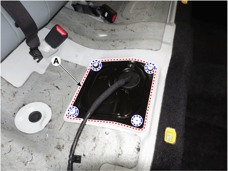
Disconnect the connectors (A, B, C).
A: Fuel Pump Connector
B: Fuel Tank Pressure Sensor Connector
C: Fuel Feed Tube Quick Connector
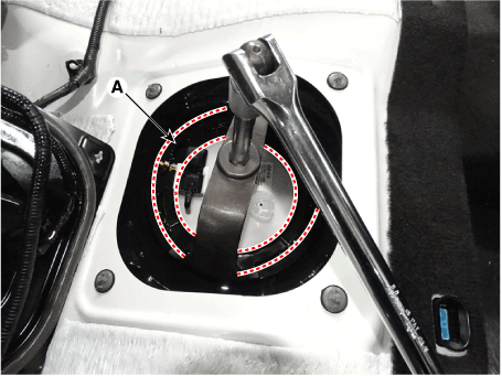
Remove the fuel pump after removing the plate cover (A) using the stainless steel tool (09310-B8100).
Installation
Install in the reverse order of removal.
Test yourself
A quick Kia Optima DL3 quiz: every answer comes with an explanation and a link to the manual page.