Engine Control System/Fuel System
DC-DC Converter
In this manual: Engine Control System/Fuel System
4steps
~24min
2/5difficulty
Done 0 of 4
Description and Operation
Description
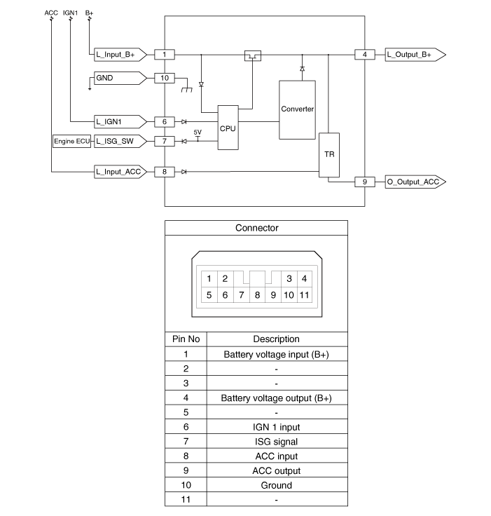
Due to a significantly more frequent occurrence of starting operations, the resulting electrical load often leads to voltage dips in the vehicle network. To stabilize the power supply for some voltage-sensitive electrical components, a DC-DC converter is used together with the ISG function. The DC-DC converter supplies a constant voltage to the relay, which also remains constant during the starting operation. The DC-DC converter is installed at the rear of the glove box. Using the input voltage and starter relay signals, the electronics decide whether power is supplied to the output through the bypass or through the DC-DC converter. In bypass mode, the vehicle network voltage is not supplied through the DC-DC converter but is passed directly to the outputs. In the boost phase, the vehicle voltage is adapted.Operating Principle

Components and Component Location
Component Location
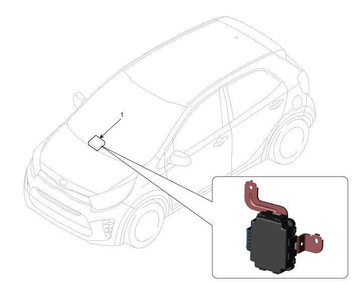
| 1. DC/DC Converter |
Circuit Diagrams
Wiring Diagram
Repair Procedures
Removal
- Turn the ignition switch OFF and disconnect the negative (-) battery terminal.
- Remove the lower crash pad panel. (Refer to Body (Interior and Exterior) - "Lower Crash Pad Panel")
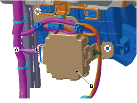
- Disconnect the DC/DC converter connector (A).
- Remove the DC-DC converter (B) after removing the nut and bolt. DC-DC converter mounting nut: 4.0–6 N·m
Installation
- Install in the reverse order of removal.
Test yourself
A quick Kia Picanto JA quiz: every answer comes with an explanation and a link to the manual page.
Was this page helpful?