Piston and Connecting Rod
Repair Procedures
Disassembly
Remove the engine assembly from the vehicle.
(See Engine and Transaxle Assembly - "Engine and Transaxle Assembly")
Remove the transaxle assembly from the engine assembly.
· Manual Transaxle
(See Manual Transaxle System - Manual Transaxle)
· Automatic Transaxle
(Refer to Automatic Transmission System - Automatic Transmission)
Remove the drive plate or flywheel.
· Automatic Transaxle
(Refer to Cylinder Block Assembly - "Drive Plate")
· Manual Transaxle
(Refer to Cylinder Block Assembly - Flywheel)
Install the engine on an engine stand for disassembly.
Remove the timing chain.
(See Timing System - Timing Chain)
Remove the intake manifold.
(See Intake and Exhaust System - Intake Manifold)
Remove the exhaust manifold.
(See Intake and Exhaust System - Exhaust Manifold)
Remove the cylinder head assembly.
(See Cylinder Head Assembly - Cylinder Head)
Remove the water outlet pipe.
(See Cooling System - Thermostat)
Remove the water temperature control assembly.
(See Cooling System - Thermostat)
Remove the oil pan and oil screen.
(See Lubrication System - Oil Pan)
Remove the ladder frame.
(Refer to Cylinder Block - Cylinder Block)
Check the connecting rod side clearance.
Remove the connecting rod caps and inspect the oil clearance.
Check the oil clearance of the connecting rod cap.
Remove the piston and connecting rod assembly.
Using a ridge reamer, remove all carbon from the top of the cylinder.
Remove the connecting rod cap (A).
Push the piston and connecting rod assembly (B) and upper bearing through the top of the cylinder block.
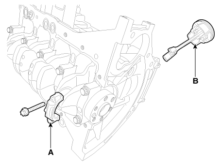
Check the fit between the piston and piston pin.
Try to move the piston back and forth on the piston pin. If any movement is felt, replace the piston and piston pin as a set.
Remove the piston rings.
Using a piston ring expander, remove the 2 compression rings.
Remove the 2 side guides and the spacer by hand.
Remove the connecting rod from the piston.
Using a press, remove the piston pin from the piston.
Press-fit load: 150–750 kg (331–1653 lb)
Inspection
Connecting Rod
Check the connecting rod side clearance.
Using a feeler gauge, measure the connecting rod side clearance while moving the connecting rod back and forth.
Standard clearance: 0.10–0.25 mm (0.0039–0.0098 in.)
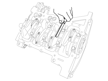
If out of specification, install a new connecting rod.
If still out of specification, replace the crankshaft.
Check the connecting rod bearing oil clearance.
Make sure the alignment marks on the connecting rod and cap are aligned to ensure correct assembly.
Remove the 2 connecting rod cap bolts.
Remove the connecting rod cap and lower bearing.
Clean the connecting rod journal and bearing.
Place a piece of Plastigage on the crankshaft journal.
Install the lower bearing and cap onto the connecting rod, then tighten the bolts.
Tightening torque: 11–15 N·m + 88 - 92°
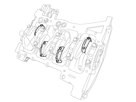
Remove the 2 bolts, connecting rod cap and lower bearing.
Measure the Plastigage at its widest point.
Connecting rod bearing oil clearance:
0.018–0.036 mm (0.0007–0.0014 in.)
Connecting rod bearing oil clearance including big end bore expansion deformation:
0.027–0.052 mm (0.0011–0.0020 in.)
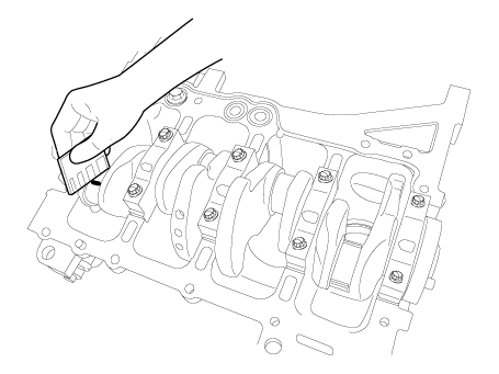
If the Plastigage is too wide or too narrow, remove the upper and lower bearings, then install new bearings with the same color code (see connecting rod bearing selection table). Recheck the oil clearance.
If the Plastigage shows the clearance is still incorrect, try the next larger or smaller bearing. (See connecting rod bearing selection table.) Recheck the oil clearance.
Location of connecting rod mark
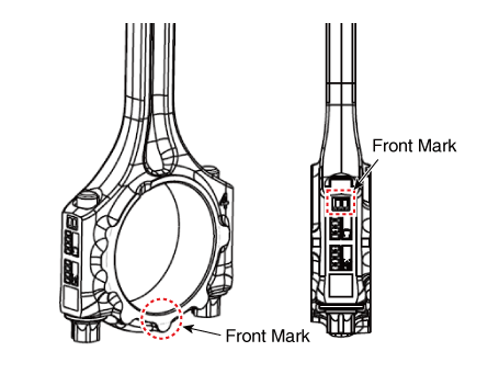
Connecting Rod Identification
Rating Mark Connecting rod inside diameter 0 A 42.000 - 42.006 mm
(1.6535–1.6540 in.)1 B 42.006 - 42.012 mm
(1.6537–1.6540 in.)2 C 42.012 - 42.018 mm
(1.6540–1.6542 in.)
Location of Mark on Crankshaft Journal

Crankshaft journal identification
Grade Mark Crankshaft Journal Outer Diameter I 1 38.966 - 38.972 mm
(1.5340–1.5343 in.)II 2 38.960 - 38.966 mm
(1.5338–1.5340 in.)III 3 38.954 - 38.960 mm
(1.5336–1.5338 in.)
Location of Connecting Rod Bearing Mark
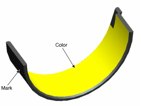
Connecting Rod Bearing Identification
Rating Color Connecting Rod Bearing Thickness A Blue 1.514 - 1.517 mm
(0.0596–0.0597 in.)B Black 1.511 - 1.514 mm
(0.0595–0.0596 in.)C None 1.508 - 1.511 mm
(0.0594–0.0595 in.)D Green 1.505 - 1.508 mm
(0.0593–0.0594 in.)E Yellow 1.502 - 1.505 mm
(0.0591–0.0593 in.)Select the bearing using the selection table.
Connecting Rod Bearing Selection Table
Connecting Rod Bearing Connecting Rod Mark 0(A) 1(B) 2(C) Crankshaft Journal Mark I (1) E (Yellow) D (green) C (None) II(2) D (green) C (None) B (Black) III(3) C (None) B (Black) Blue)
Piston
Clean the Piston
Using a gasket scraper, remove carbon deposits from the top of the piston.
Using a ring groove cleaning tool, clean the piston ring grooves.
Using solvent and a brush, thoroughly clean the piston.
The standard piston outside diameter is measured at 30.0 mm (1.21 in.) from the piston top surface.
Standard diameter: 71.970–72.000 mm (2.8334–2.8346 in.)
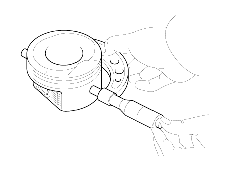
Check the cylinder bore size code on the cylinder block.
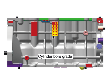
Cylinder Bore Diameter Grades
Rating Size code Cylinder Inner Diameter a A 72.00 - 72.01 mm
(2.8346–2.8350 in.)D B 72.01 - 72.02 mm
(2.8350–2.8354 in.)c C 72.02 - 72.03 mm
(2.8354–2.8358 in.)Check the piston size code (A) and front mark (B) on the piston top face.
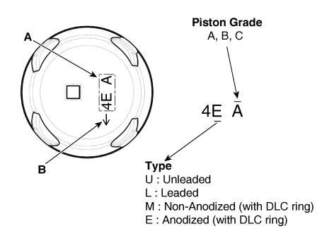
Piston Outside Diameter Grades
Rating Size code Piston Outer Diameter a A 71.970 - 71.980 mm
(2.8334–2.8338 in.)D B 71.980 - 71.990 mm
(2.8338–2.8342 in.)c C 71.990 - 72.000 mm
(2.8342–2.8346 in.)Select a piston that matches the cylinder bore size class.
Clearance: 0.02–0.04 mm (0.0008–0.0016 in.)
Piston Rings
Calculate the difference between the cylinder bore diameter and the piston diameter.
Piston-to-cylinder clearance: 0.02–0.04 mm (0.0008–0.0016 in.)
Inspect the piston ring side clearance.
Using a feeler gauge, measure the clearance between a new piston ring and the ring groove wall.
Piston Ring Groove Width
No. 1: 1.035–1.05 mm (0.0407–0.0413 in.)
No. 2: 1.23–1.25 mm (0.0484–0.0492 in.)
Oil Ring: 1.995–2.010 mm (0.0785–0.0791 in.)
Piston Ring Width
No. 1: 0.97–0.985 mm (0.0381–0.0387 in.)
No. 2: 1.17–1.19 mm (0.0460–0.0468 in.)
Oil ring: 1.925–1.955 mm (0.0758–0.0770 in.)
Piston Ring Side Clearance
No. 1: 0.05–0.08 mm (0.0019–0.0031 in.)
No. 2: 0.04–0.08 mm (0.0015–0.0031 in.)
Oil ring: 0.040–0.850 mm (0.0015–0.0335 in.)
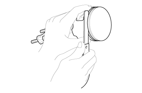
If the clearance is greater than the maximum, replace the piston.
Inspect the piston ring end gap.
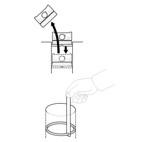
To measure the piston ring end gap, insert the piston ring into the cylinder bore. Position the ring at a right angle to the cylinder wall by lightly pushing it with the piston. Measure the gap with a feeler gauge. If the gap exceeds the service limit, replace the piston ring. If the gap is too large, check the cylinder bore diameter against the wear limit. If the bore exceeds the service limit, replace the cylinder block.
Piston Ring End Gap
No. 1: 0.13–0.18 mm (0.0051–0.0071 in.)
No. 2: 0.25–0.40 mm (0.0098–0.0157 in.)
Oil ring: 0.10–0.40 mm (0.0039–0.0157 in.)
Piston Pin
Measure the piston pin diameter.
Piston pin outside diameter:
18.000–18.003 mm (0.7086–0.7087 in.)
Piston pin hole diameter:
18.013–18.017 mm (0.7092–0.7093 in.)
Connecting rod small end inside diameter:
17.974–17.985 mm (0.7076–0.7080 in.)
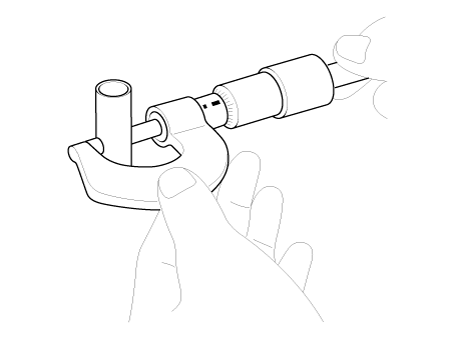
Measure the piston pin-to-piston clearance.
Piston pin to piston clearance: 0.010–0.017 mm (0.00039–0.00067 in.)
Check the difference between the piston pin outer diameter and the connecting rod small end inner diameter.
Piston pin-to-connecting rod fit:
0.015–0.029 mm (0.0006–0.0011 in.)
Installation
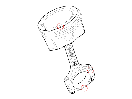
Assemble the piston and connecting rod.
For installation, use a hydraulic press.
The front mark on the piston and the front mark on the connecting rod must face the timing chain side of the engine.
Install the piston rings.
Install the oil ring expander and the 2 side rails by hand.
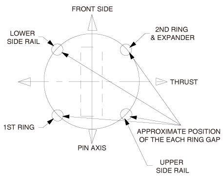
Using a piston ring expander, install the 2 compression rings with the code mark facing up.
Position the piston rings so that the ring end gaps are as shown in the illustration.
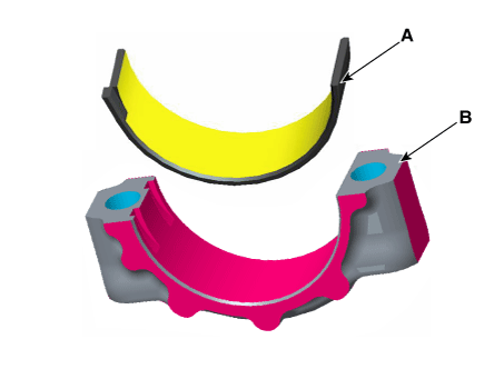
Install the connecting rod bearings.
Align the bearing protrusion with the groove in the connecting rod and connecting rod cap.
Install the bearings (A) in the connecting rod and connecting rod cap (B).
Install the piston and connecting rod assembly.
Install the ring compressor, check that the bearings are seated correctly, then insert the piston into the cylinder and tap it in with the wooden handle of a hammer.
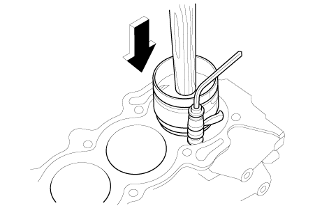
Stop after the ring compressor is released and check the connecting rod alignment before inserting the piston.
Apply engine oil to the bolt threads. Install the connecting rod caps with bearings and tighten the bolts.
Tightening torque: 11–15 N·m + 88 - 92°
Check the connecting rod side clearance.
Assemble the remaining components in the reverse order of removal.
Test yourself
A quick Kia Rio YB quiz: every answer comes with an explanation and a link to the manual page.