Smart Key Unit
Components and Component Location
Components

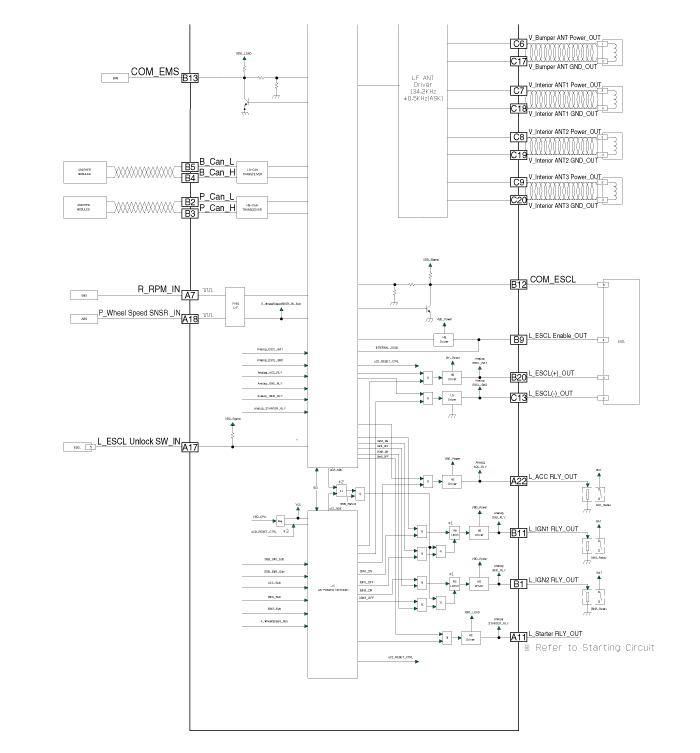
Connector Pin Information
| No. | Connector A | Connector B | Connector C |
| 1 | - | IGN2 Relay Output | Battery (+) Signal |
| 2 | SSB Switch1 signal_input | P-CAN (Low) | - |
| 3 | driver's outside door handle switch_input | P-CAN (High) | Immobilizer antenna (power)_output |
| 4 | - | C-CAN (High) | Driver's outside handle antenna (power)_output |
| 5 | - | C-CAN (Low) | Passenger's outside handle antenna (power)_output |
| 6 | - | SSB amber illumination_output | Bumper antenna (power)_output |
| 7 | RPM Signal_input | - | Internal antenna 1 (power)_output |
| 8 | Start Signal Feedback_Input | SSB (+) Illumination_Output | Interior antenna 2 (power) output |
| 9 | IGN2 | ESCL Enable_output | Interior antenna 3 (power) output |
| 10 | - | Battery (+) Power | - |
| 11 | Starter Relay Output | IGN1 Relay Output | - |
| 12 | Ground_Power1 | ESCL (COM) | - |
| 13 | SSB Switch2 signal_input | Ground (COM) | ESCL_Ground (-)_output |
| 14 | Auxiliary door handle outside switch input | - | Immobilizer antenna (ground) output |
| 15 | - | SSB illumination (-) output | Driver outside handle antenna (ground) output |
| 16 | AT: "P" Position input MT: Clutch switch input |
SSB illumination (blue) output SSB illumination (red) output |
Passenger outside handle antenna (ground) output |
| 17 | ESCL unlock switch_input | - | Bumper antenna (ground) output |
| 18 | Wheel Speed Sensor_Input | External Buzzer_Output | Interior antenna 1 (ground) output |
| 19 | ACC Signal_input | - | Interior antenna 2 (ground) output |
| 20 | IGN1 | ESCL (+)_Output | Interior antenna 3 (ground) output |
| 21 | Brake Switch_Input | - | |
| 22 | ACC Relay_output | Ground_Power2 |
Circuit Diagrams
Wiring Diagram

Repair Procedures
Removal
Smart Key Unit
Disconnect the negative (-) battery terminal.
Remove the glove box.
(See Body - Glove Box)
Disconnect the connectors (A), then remove the smart key unit (B).

Remove the smart key unit (A) after loosening the nuts.
Interior 1 Antenna
Disconnect the negative (-) battery terminal.
Remove the heater and A/C control unit.
(Refer to Heating, Ventilation, Air Conditioning - "Heater and A/C Control"). Unit (Manual)
(Refer to Heating, Ventilation, Air Conditioning - "Heater and A/C Control"). Unit (FATC)
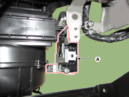
Loosen the mounting screws and disconnect the connector (B), then remove the interior antenna 1 (A).
Interior 2 Antenna
Disconnect the negative (-) battery terminal.
Remove the floor console assembly.
(Refer to Body - Floor Console Assembly)
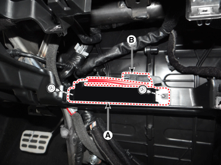
Disconnect the interior antenna 2 connector (A).

Loosen the mounting screws, then remove the interior antenna 2 (A).

Trunk Antenna
Disconnect the negative (-) battery terminal.
Remove the rear crossmember trim.
(Refer to Body - "Rear Crossmember Trim")
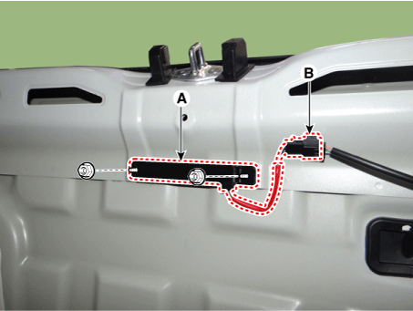
Loosen the mounting nuts and disconnect the connector (B), then remove the tailgate antenna (A).
Rear Bumper Antenna
Disconnect the negative (-) battery terminal.
Remove the rear bumper assembly.
(Refer to Body - "Rear Bumper Assembly")
Loosen the mounting screws and disconnect the connector (B), then remove the rear bumper antenna (A).
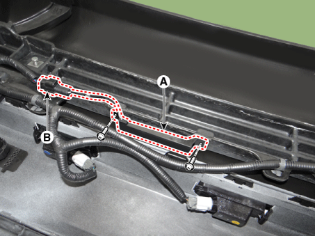
Buzzer
Disconnect the negative (-) battery terminal.
Remove the front bumper assembly.
(Refer to Body - "Front Bumper Assembly")
Remove the buzzer (A) after disconnecting the connector.

Outside Door Handle
Disconnect the negative (-) battery terminal.
Remove the front door outside handle.
(Refer to Body - "Front Door Outside Handle")
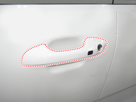

Liftgate Opener Switch
Disconnect the negative (-) battery terminal.
Remove the rear view camera unit.
(Refer to Body Electrical System - "Rear View Camera System")
Loosen the mounting screws, then remove the luggage compartment door opener switch assembly (A).

Inspection
Smart Key Unit
(Refer to Smart Key System - Smart Key Diagnosis)
Smart Key Switch
(Refer to Smart Key System - Smart Key Diagnosis)
Antenna
(Refer to Smart Key System - Smart Key Diagnosis)
Outside Door Handle
Disconnect the front door outside handle connector (A).

Check the continuity of the circuit between terminals No. 2 and No. 4.
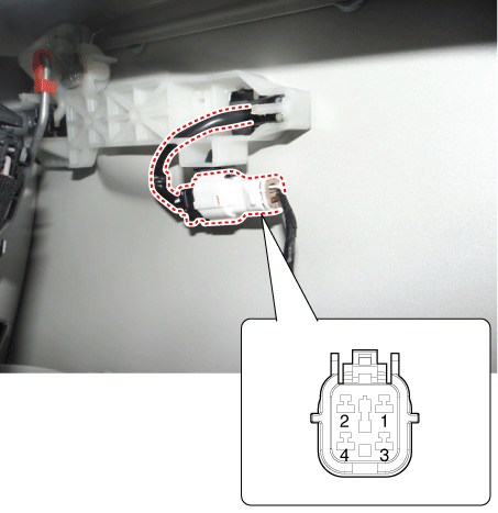
No. Description 1 Door Antenna 1 2 Door Lock/Unlock Switch 1 3 Door Antenna 2 4 Door Lock/Unlock Switch 2
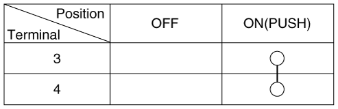
Liftgate Opener Switch
Check the continuity between the terminals of the liftgate opener switch.
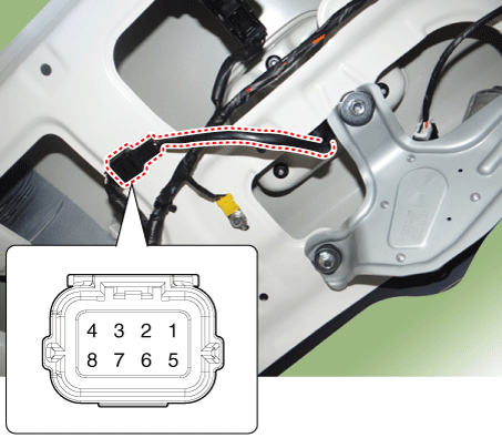
If continuity is not as specified, inspect the switch.
Installation
Smart Key Unit
Install the smart key unit after connecting the connectors.
Install the glove box.
Connect the negative (-) battery terminal and check the smart key system.
Interior 1 Antenna
Install the interior 1 antenna.
Install the heater and A/C control unit.
Connect the negative (-) battery terminal and check the smart key system.
Interior 2 Antenna
Install the interior 2 antenna.
Install the floor console assembly.
Connect the negative (-) battery terminal and check the smart key system.
Trunk Antenna
Install the antenna to the tailgate.
Install the rear cross trim.
Connect the negative (-) battery terminal and check the smart key system.
Rear Bumper Antenna
Install the rear bumper antenna.
Install the rear bumper assembly.
Connect the negative (-) battery terminal and check the smart key system.
Buzzer
Install the buzzer.
Install the front bumper assembly.
Connect the negative (-) battery terminal and check the smart key system.
Outside Door Handle
Install the front door outside handle.
Connect the negative (-) battery terminal and check the smart key system.
Liftgate Opener Switch
Install the luggage compartment door opener switch assembly.
Install the rear view camera unit.
Install the rear door outside handle assembly.
Connect the luggage compartment door outside handle assembly connector.
Install the liftgate trim.
Connect the negative (-) battery terminal and check the smart key system.
Test yourself
A quick Kia Rio YB quiz: every answer comes with an explanation and a link to the manual page.