P2127, P2128 APP sensor
DTC Logic
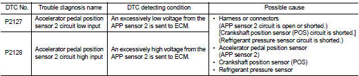
DTC DETECTION LOGIC
DTC CONFIRMATION PROCEDURE
1.PRECONDITIONINGIf DTC Confirmation Procedure has been previously conducted, always turn ignition switch OFF and wait at least 10 seconds before conducting the next test.
TESTING CONDITION:Before performing the following procedure, confirm that battery voltage is more than 10 V at idle.
>> GO TO 2.
2.PERFORM DTC CONFIRMATION PROCEDURE 1. Start engine and let it idle for 1 second.2. Check DTC.
Is DTC detected? YES >> Go to EC-751, "Diagnosis Procedure".
NO >> INSPECTION END
Diagnosis Procedure
1.CHECK GROUND CONNECTION 1. Turn ignition switch OFF.2. Check ground connection E38. Refer to Ground Inspection in GI-44, "Circuit Inspection".
Is the inspection result normal? YES >> GO TO 2.
NO >> Repair or replace ground connection.
2.CHECK APP SENSOR 2 POWER SUPPLY CIRCUIT-I 1. Disconnect accelerator pedal position (APP) sensor harness connector. 2. Turn ignition switch ON.3. Check the voltage between APP sensor harness connector and ground.
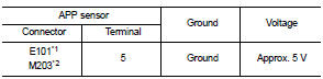
*1: LHD models or RHD models with CVT *2: RHD models with M/T
Is the inspection result normal? YES >> GO TO 6.
NO >> GO TO 3.
3.CHECK APP SENSOR 2 POWER SUPPLY CIRCUIT-II 1. Turn ignition switch OFF. 2. Disconnect ECM harness connector.3. Check the continuity between APP sensor harness connector and ECM harness connector.

*1: LHD models or RHD models with CVT *2: RHD models with M/T
Is the inspection result normal? YES >> GO TO 4.
NO >> Repair open circuit or short to ground or short to power in harness or connectors.
4.CHECK SENSOR POWER SUPPLY CIRCUITCheck harness for short to power and short to ground, between the following terminals.

*1: LHD models or RHD models with CVT *2: RHD models with M/T
Is the inspection result normal? YES >> GO TO 5.
NO >> Repair short to ground or short to power in harness or connectors.
5.CHECK COMPONENTSCheck the following.
• Crankshaft position sensor (POS) (Refer to EC-658, "Component Inspection".) • Refrigerant pressure sensor (Refer to EC-790, "Diagnosis Procedure".)
Is the inspection result normal? YES >> GO TO 10.
NO >> Replace malfunctioning component.
6.CHECK APP SENSOR 2 GROUND CIRCUIT FOR OPEN AND SHORT 1. Turn ignition switch OFF. 2. Disconnect ECM harness connector.3. Check the continuity between APP sensor harness connector and ECM harness connector.
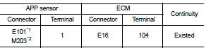
*1: LHD models or RHD models with CVT *2: RHD models with M/T
4. Also check harness for short to ground and short to power.
Is the inspection result normal? YES >> GO TO 7.
NO >> Repair open circuit or short to ground or short to power in harness or connectors.
7.CHECK APP SENSOR 2 INPUT SIGNAL CIRCUIT FOR OPEN AND SHORT1. Check the continuity between APP sensor harness connector and ECM harness connector.

*1: LHD models or RHD models with CVT *2: RHD models with M/T
2. Also check harness for short to ground and short to power.
Is the inspection result normal? YES >> GO TO 8.
NO >> Repair open circuit or short to ground or short to power in harness or connectors.
8.CHECK APP SENSORRefer to EC-753, "Component Inspection".
Is the inspection result normal? YES >> GO TO 10.
NO >> GO TO 9.
9.REPLACE ACCELERATOR PEDAL ASSEMBLYReplace accelerator pedal assembly. Refer to ACC-3, "Exploded View".
>> INSPECTION END
10.CHECK INTERMITTENT INCIDENTRefer to GI-42, "Intermittent Incident".
>> INSPECTION END
Component Inspection
1.CHECK ACCELERATOR PEDAL POSITION SENSOR 1. Reconnect all harness connectors disconnected. 2. Turn ignition switch ON.3. Check the voltage between ECM harness connector and ground.
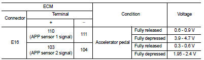
Is the inspection result normal? YES >> INSPECTION END
NO >> GO TO 2.
2.REPLACE ACCELERATOR PEDAL ASSEMBLYReplace accelerator pedal assembly. Refer to ACC-3, "Exploded View".
>> INSPECTION END