Transmission
Automatic gearbox: Removal - Refitting
In this manual: Transmission
~7min read
F4R or K4M, and DP0
Essential special tools |
|
| Rou. 604-01 | Hub holder |
| Tav. 476 | Ball joint extractor |
| Mot. 1453 | Multi-adjustable engine mounting bracket, with retaining straps |
| Bvi. 1531 | Flywheel centring tool for automatic transmission torque converter |
Essential equipment |
| component spring compressor |
Tightening torques |
|
| wheel bolts | 11 daN.m |
| brake caliper guide pin bolts | 0.7 daN.m |
| steering ball joint nut | 3.7 daN.m |
| lower ball joint nut | 6.2 daN.m |
| torque reaction rod bolt on subframe | 10.5 daN.m |
| gearbox bellhousing and starter bolts | 4.4 daN.m |
| pendulum support nut on gearbox | 6.2 daN.m |
| steering track rod end nut | 6.2 daN.m |
| torque converter to drive plate nut | 3.7 daN.m |
| modular connector support bolt | 2 daN.m |
| engine speed sensor mounting screw | 1 daN.m |
| torque reaction rod bolt on K engine | 10.5 daN.m |
| torque reaction rod bolt on F engine | 18 daN.m |
| pendulum mount nut on bump stop | 18 daN.m |
| battery cover | 0.4 daN.m |

Features of vehicles fitted with a driver airbag
WARNINGTo avoid any risk of damaging the clockspring, observe the following instructions:
- Before disconnecting the steering column from the steering rack, the steering wheel must be locked in the straight-ahead position using the steering wheel lock for the entire duration of the procedure,
- Any doubt about the correct centring of the clock spring requires removing the steering wheel to apply the centring method (see Chapter Controls - Signalling). In this case, only suitably trained qualified personnel may carry out the work.
REMOVAL
- Position the vehicle on a two-post lift.
- Remove the engine covers.
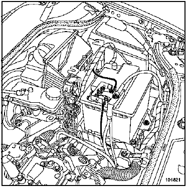
- Disconnect the battery, starting with the negative terminal.
- Remove:
- the air intake duct,
- the battery,
- the battery tray,
- the injection ECU and its bracket,
- the air intake hose,
- the wiring harness mountings.
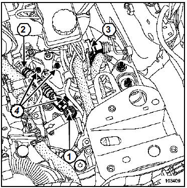
- Remove:
- the ball joint (1) of the multifunction switch cable using the tool,
- the wiring (2) of the multifunction switch cable by releasing the cable sheath lock,
- the wiring harness mountings.
- Disconnect:
- the engine speed sensor,
- the connector (3) by releasing the connector lock.
- Remove the mounting bolts (4) of the modular connector bracket.
Protect the connector by slipping it into a waterproof plastic bag.
K4M
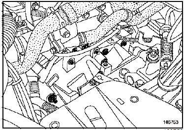
- Remove the engine speed sensor.
F4R
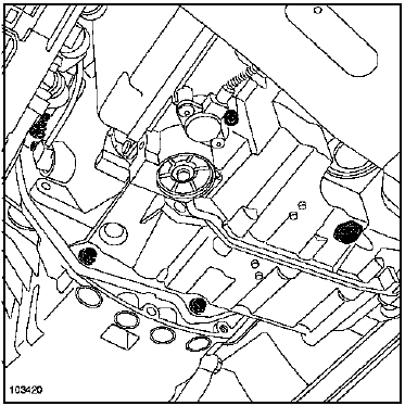
- Remove the engine speed sensor.
- Fit hose clamps.
- Disconnect the intercooler.
- Unclip the gearbox harness.
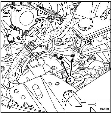
- Remove:
- the two bolts (5) of the starter motor,
- the engine undertray.
- Drain the gearbox oil.
- Remove:
- the wheels,
- the mudguards.
- Disconnect:
- the wiring of the ABS wheel speed sensors,
- the wiring of the xenon headlamp levelling sensors (if fitted).
I - LEFT-HAND SIDE OF THE VEHICLE
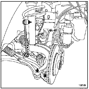
- Remove:
- the xenon headlamp sensor link (if fitted),
- the hub nut using the tool (Rou. 604-01),
- the steering track rod end, using tool (Tav. 476),
- the anti-roll bar ball joint using the tool (Tav. 476),
- the lower ball joint.
- Release the hub carrier from the driveshaft.
- Remove the left-hand driveshaft.
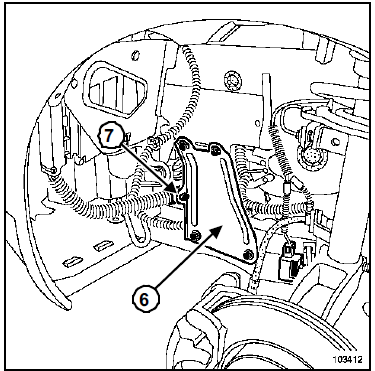
- Remove:
- the clip (7) of the gearbox ECU harness,
- the side reinforcement (6).
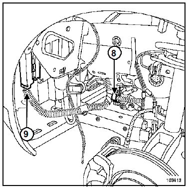
- Open the mounting tab (8) of the gearbox ECU harness.
- Disconnect connector (9) from the gearbox ECU.
II - RIGHT-HAND SIDE OF THE VEHICLE
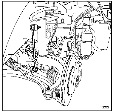
- Remove:
- the hub nut, using tool (Rou. 604-01),
- the steering track rod end, using tool (Tav. 476),
- the anti-roll bar ball joint using the tool (Tav. 476),
- the lower ball joint.
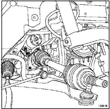
- Remove the relay bearing bracket.
- Release the hub carrier from the driveshaft.
- Remove the right-hand driveshaft.
- Tie all the cooling radiators to the upper cross member using ropes.
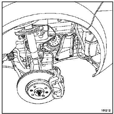
- Remove the side reinforcement.
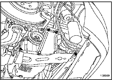
- Remove the lower radiator crossmember.
K4M
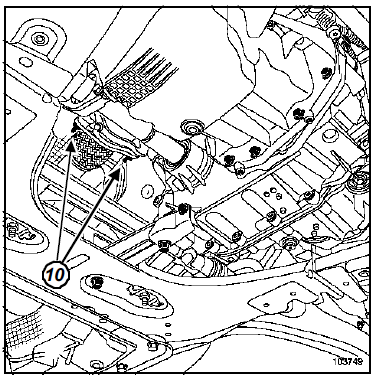
- Remove:
- the exhaust mounting nuts,
- the torque rod.
F4R
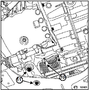
- Remove:
- the exhaust mounting nuts (10),
- the torque rod.
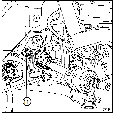
- Remove:
- the exhaust manifold / lower engine bracket,
- the starter motor mounting bolt (11),
- the starter motor,
- the three torque converter nuts.
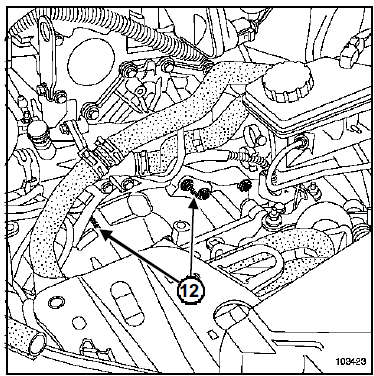
- Remove the upper gearbox bellhousing studs (12).
- Strap down the bonnet.
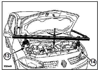
- Open the cover (13).
- Remove the cover (14).
- Fit tool (Mot. 1453).
- Remove the gearbox mount pad.
- Fit the transmission jack tool under the gearbox.
- Remove:
- the lower gearbox torque bolts,
- the gearbox mounting studs,
- the automatic gearbox.
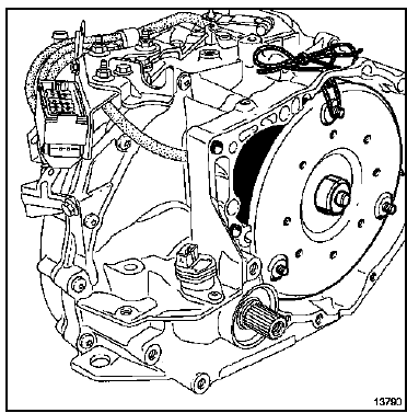
- Tie the torque converter with string to prevent it from coming off.
INSTALLATION
WARNING- Do not reuse the torque converter mounting nuts or the flywheel nuts if they have been removed: always fit new nuts.
- Check that the centring rings are in place.
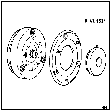
- Refit the flywheel to the torque converter using tool (Bvi. 1531).
- Refit in the reverse order of removal.
CAUTION Check that the centring sleeves are in place.
When refitting the automatic gearbox to the engine, make sure the torque converter is fully engaged on the input shaft axis.
- Tighten to the following torques:
- the wheel bolts (11 daN.m),
- the brake caliper guide pin bolts (0.7 daN.m),
- the steering ball joint nut (3.7 daN.m),
- the lower ball joint nut (6.2 daN.m),
- the torque rod bolts on the subframe (10.5 daN.m),
- the gearbox and starter motor torque bolts (4.4 daN.m),
- the pendulum mount nut on the gearbox (6.2 daN.m),
- the steering ball joint nut (6.2 daN.m),
- the torque converter nut on the drive plate (3.7 daN.m),
- the modular connector bracket bolts (2 daN.m),
- the engine speed sensor mounting bolts (1 daN.m),
- the torque rod bolts on the K engine (10.5 daN.m),
- the torque rod bolts on the F engine (18 daN.m),
- the pendulum mount nut on the mount pad (18 daN.m).
- Fill the automatic gearbox and check the level (Automatic Gearbox section, Filling - Levels, page 23A-6).
- When changing the oil, reset the self-adaptive values using command RZ005: "Self-adaptive values erasure" and reset the gearbox ECU oil ageing counter by running command CF074: "Gearbox oil change date write".
After running command RZ005, it is important to carry out a road test performing several upshifts and downshifts to store the new values.
WARNINGConnect the battery; carry out the necessary relearn procedures (Chapter Battery).
- Torque the battery cover (0.4 daN.m).
Test yourself
A quick Renault Megane quiz: every answer comes with an explanation and a link to the manual page.
Was this page helpful?