Interpreting parameters
| PR001 | CABIN TEMPERATURE |
INSTRUCTIONS
Nothing to report.
| The regulated air conditioning control unit receives the cabin temperature information via a wired link. |
| To check that this parameter is correct (without a thermometer), simply read the temperature information when the vehicle is cold (in the morning). The cabin temperature, outside temperature and engine coolant temperature must be almost equal. Another way to check the sensor is to measure its resistance value according to temperature: refer to the sensor electrical characteristics table in the "Help" chapter. |
| If the temperature displayed by this parameter appears inconsistent: carry out the diagnostic procedure for fault DF007 "Cabin temperature sensor circuit". |
AFTER REPAIR
Restart the conformity check from the beginning.
| PR006 | SOLAR LOAD |
INSTRUCTIONS
Nothing to report.
| The solar sensor improves the thermal comfort level of the air conditioning based on the solar load on the windscreen. |
| This sensor measures the solar load level and sends the information to the air conditioning control unit as a measurement in W/m2. This measurement ranges from 0 to 400 W. If the sensor constantly reads 400 W while the vehicle is in the shade (in the workshop), the sensor is faulty (maximum solar load). |
| If the value displayed by this parameter appears inconsistent: check the signal emitted by the sensor according to the solar load, by measuring between pin 2 of the sensor and ground (solar sensor electrically connected, ignition on and control panel lit). 0 W → 4.91 V |
| If the problem persists, carry out the diagnostic procedure for fault DF026 "Solar sensor circuit". |
AFTER REPAIR
Restart the conformity check from the beginning.
| PR011 | DISTRIBUTION FLAP POSITION |
INSTRUCTIONS
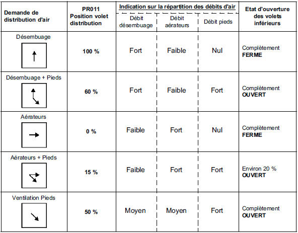
The values below are given for information only (they depend on the flap control direction).
The table below shows the control percentages of the air distribution motor as well as the opening state of the lower flaps (footwell and under-seat duct ventilation flaps). To view the lower flaps, the right and left lower air ducts must be removed.
Values checked with engine off and air conditioning in manual mode (tolerance ±5%).
AFTER REPAIR
Restart the conformity check from the beginning.
| PR012 | BLEND FLAP POSITION |
INSTRUCTIONS
Nothing to report.
| The blend flap varies according to the temperature demand or automatically if the air conditioning is in automatic mode. The blend motor is not fitted with a position feedback potentiometer. This parameter therefore gives an indication of the flap position according to the motor control by the regulated air conditioning control unit. As indicated in the conformity check, at full cold (15 °C) the parameter shows 0% and at full hot (27 °C) the parameter shows 100%. |
| If the value displayed by this parameter appears inconsistent, or if the parameter is consistent but the temperature of the blown air does not change according to the user demand: carry out the diagnostic procedure for fault DF010 "Blend motor circuit", or refer to fault tree ALP 6 "No heating" or ALP 8 "No cooling" depending on the customer symptom (these fault trees are in chapter 62A "Air conditioning"). |
AFTER REPAIR
Restart the conformity check from the beginning.
| PR019 | CABIN GMV PWM SETPOINT |
INSTRUCTIONS
The values below are given for information only.
Values checked with engine off and engine running with air conditioning in manual mode (tolerance ±5%).
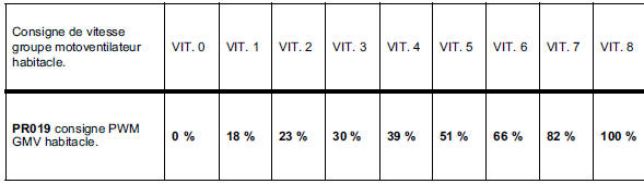
If the values mentioned above are correct but the cabin fan does not operate, refer to the fault tree: ALP 5 "No cabin ventilation".
AFTER REPAIR
Restart the conformity check from the beginning.
| PR092 | BATTERY VOLTAGE |
INSTRUCTIONS
Nothing to report.
| This parameter indicates the supply voltage of the regulated air conditioning control unit. This parameter must show a voltage equal to: 10.5 < X < 14.4 V. If the voltage is not within the specified range: disconnect connector A (12-way) from the air conditioning control unit in order to check the insulation, continuity and absence of parasitic resistance of the wiring:Control unit connector A pin 10 → + auxiliary supply (7.5 A fuse of the Protection and Switching Unit) Repair if necessary. |
| If the wiring is compliant but the problem persists: carry out a diagnosis of the electrical charging circuit. |
AFTER REPAIR
Restart the conformity check from the beginning.
| PR121 | BLOWN AIR TEMPERATURE SETPOINT |
INSTRUCTIONS
Nothing to report
This parameter manages the heating of the cabin. This setpoint is calculated by the regulated air conditioning control unit based on the cabin temperature, the outside temperature and the engine coolant temperature.This setpoint controls the blend motor and requests activation of the cabin air heating resistors (to reach the temperature requested by the user as quickly as possible, in order to rapidly optimise cabin comfort).
For the Cabin Central Unit to control the cabin air heating resistors, the following conditions must be met:- Engine running,
- Cabin blower motor running (speed 1 minimum),
- User temperature setpoint above 20 °C (or automatic mode requested),
- Blown air temperature setpoint above 65 °C,
- Cabin temperature below 10 °C,
- Outside temperature below 5 °C,
- Engine coolant temperature below 65 °C,
- Injection enabled (ET019 "number of RCH authorised by injection" < 1),
- Alternator enabled (ET018 "number of RCH authorised by alternator" < 1).
NOTE:
- States ET017, ET018 and ET019 are reported by the Cabin Control Unit (see air conditioning function conformity check: chapter 62A).
- The values listed above are average values. The Cabin Control Unit calculates the number of Cabin Heating Resistors to be switched on (ET017 "number of RCH required") by cross-referencing this information.
AFTER REPAIR
Restart the conformity check from the beginning.
Test yourself
A quick Renault Megane quiz: every answer comes with an explanation and a link to the manual page.