Automatic High Beam Main Switch
Components
COMPONENTS
ILLUSTRATION
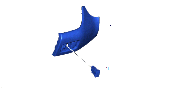
*1 |
AUTOMATIC HIGH BEAM SWITCH |
*2 |
INSTRUMENT CLUSTER FINISH PANEL SUB-ASSEMBLY |
Removal
REMOVAL
PROCEDURE
1. REMOVE COMBINATION METER FINISH PANEL SUB-ASSEMBLY
Click here
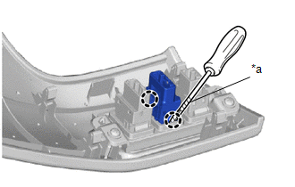
2. REMOVE AUTOMATIC HIGH BEAM SWITCH
(a) Using a screwdriver with its tip wrapped in protective tape, release the claws to remove the automatic high beam switch. |
|
Inspection
INSPECTION
PROCEDURE
1. INSPECT AUTOMATIC HIGH BEAM SWITCH
(a) Check the resistance.
(1) Measure the resistance according to the value(s) shown in the table below. Standard resistance:
If the result is not as specified, replace the automatic high beam switch. |
|
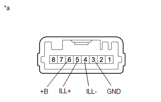
(b) Check the illumination.
(1) Apply battery voltage to the automatic high beam switch and check that it illuminates.
OK:
Condition | Specified Condition |
|---|---|
Battery positive (+) → Terminal 5 (+) (ILL+) Battery negative (-) → Terminal 4 (ILL-) |
Comes on |
If the result is not as specified, replace the automatic high beam switch.
Installation
INSTALLATION
PROCEDURE
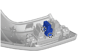
1. INSTALL AUTOMATIC HIGH BEAM SWITCH
(a) Engage the claws to install the automatic high beam switch, as shown in the illustration. |
 |
2. INSTALL COMBINATION METER FINISH PANEL SUB-ASSEMBLY
Click here