Manual Headlight Level Control System
Precautions
PRECAUTION
IGNITION SWITCH TERMS
The type of ignition switch used varies depending on vehicle specifications. The terms listed in the table below are used in this section.
Term | Ignition Switch (Position) | Engine Switch (Condition) |
|---|---|---|
Ignition Switch in OFF position |
LOCK |
OFF (Locked) |
Ignition Switch in ACC position |
ACC |
ON (ACC) |
Ignition Switch in ON position |
ON |
ON (IG) |
Starting the engine |
START |
ON (Starting) |
Component Locations
COMPONENT LOCATIONS
ILLUSTRATION
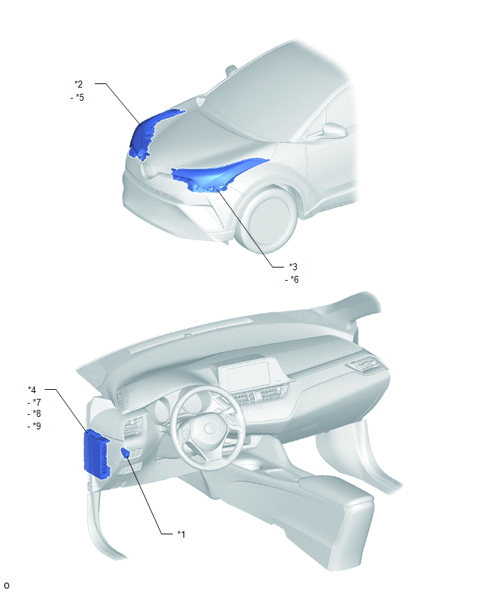
*1 |
HEADLIGHT LEVEL CONTROL SWITCH |
*2 |
HEADLIGHT UNIT ASSEMBLY RH |
*3 |
HEADLIGHT UNIT ASSEMBLY LH |
*4 |
INSTRUMENT PANEL JUNCTION BLOCK ASSEMBLY |
*5 |
RH HEADLIGHT LEVELING MOTOR |
*6 |
LH HEADLIGHT LEVELING MOTOR |
*7 |
TAIL FUSE |
*8 |
TAIL LAMP RELAY |
*9 |
PANEL FUSE |
- |
- |
System Description
SYSTEM DESCRIPTION
MANUAL HEADLIGHT LEVEL CONTROL SYSTEM
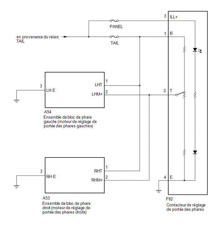
The manual headlight level control system controls each headlight leveling motor based on the operation of the headlight level control switch in order to change the reflection angle of the headlights.
System Diagram
SYSTEM DIAGRAM
How to Use Troubleshooting
PRECAUTION / NOTICE / HINT
HINT:
Follow the procedure below to troubleshoot the manual headlight level control system.
PROCEDURE
VEHICLE BROUGHT TO WORKSHOP
|

CUSTOMER PROBLEM ANALYSIS AND SYMPTOM CONFIRMATION
|
CHECK BATTERY VOLTAGE
(a) Measure the battery voltage.
Standard voltage:
11 à 14 V
If the voltage is below 11 V, charge or replace the battery before proceeding to the next step.
|
SYMPTOM TROUBLESHOOTING TABLE
(a) Refer to the Symptom Troubleshooting Table.
Click here
|
ADJUST, REPAIR OR REPLACE
|
CONFIRMATION TEST
| NEXT |  |
END |