Installation
INSTALLATION
PRECAUTION / NOTICE / HINT
NOTICE:
- As the right and left front hoses are not interchangeable, check the part number when installing the front hoses.
- If reusing the front hoses, use the identification marks made during removal to install each front hose in its original position.
HINT:
- Repeat the same procedure for the right side and the left side.
- The following procedure applies to the left side.
PROCEDURE
1. INSTALL FRONT HOSE
NOTICE:
When installing the front hose, reduce the twist in the hose.
(a) Install a new clip to the front hose. NOTICE:
|
|
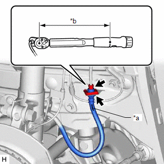
(b) Using a flare nut wrench, connect the brake tube to the front hose while holding the front hose with a wrench.
Torque:
Specified torque:
15.2 N·m {155 kgf·cm, 11 ft·lbf}
NOTICE:
- Do not kink or damage the brake tube.
- Make sure that no foreign matter, such as dirt or dust, enters the brake tube through the connection points.
HINT:
- Calculate the torque wrench reading when changing the torque wrench lever length.
Click here

- When using a flare nut wrench (lever arm length of 22 mm (0.866 in.)) + torque wrench (lever arm length of 162 mm (6.38 in.)): 13.4 N*m (137 kgf*cm, 10 ft*lbf)
(c) Engage the 2 claws to install the front speed sensor bracket.
NOTICE:
Do not twist the front speed sensor wire harness when installing it.
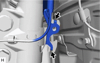
 |
Hook |
(d) Install the front speed sensor and front hose to the shock absorber sub-assembly with the bolt. Torque: 29 N·m {296 kgf·cm, 21 ft·lbf} NOTICE: Do not twist the front hose when installing it. |
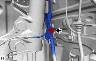 |
(e) Connect the front hose to the front disc brake wheel cylinder sub-assembly using a new union bolt and a new gasket.
Torque:
29 N·m {296 kgf·cm, 21 ft·lbf}
NOTICE:
- Install the front flexible hose lock correctly in the lock hole of the front disc brake wheel cylinder assembly.
- Do not twist the front hose when installing it.
2. BLEED BRAKE LINE
Click here
3. INSTALL FRONT WHEEL
Click here