Diagnostic System
DIAGNOSTIC SYSTEM
CHECK DLC3
(a) Check DLC3.
Click here
SRS WARNING LIGHT OPERATION
(a) Initial check
(1) Turn the ignition switch OFF. Wait at least 2 seconds, then turn the ignition switch ON. The SRS warning light comes on for approximately 6 seconds and the SRS airbag system diagnosis is performed.
HINT:
If a malfunction is detected during the initial check, the SRS warning light remains on for approximately 6 seconds after the initial check period.
(b) Continuous monitoring
(1) After the initial check, the airbag sensor assembly continuously monitors the SRS airbag system for malfunctions.
HINT:
If any malfunctions are detected during the continuous monitoring, the airbag sensor assembly indicates the malfunction as follows:- The SRS warning light comes on.
- The SRS warning light turns off, then comes on again. This indicates a drop in the power supply voltage. The SRS warning light turns off 10 seconds after the power supply voltage returns to normal.
(c) Summary
(1) When the SRS airbag system is normal:
The SRS warning light comes on only during the initial check period, for approximately 6 seconds after the ignition switch is turned ON.
(2) When the SRS airbag system is malfunctioning:
- The SRS warning light remains on after the initial check period ends.
- The SRS warning light turns off after the initial check period, but then comes on again during continuous monitoring.
- The SRS warning light does not come on when the ignition switch is turned from OFF to ON.
HINT:
The SRS warning light remains on even if an airbag or pretensioner has deployed.
SRS WARNING LIGHT CHECK
(a) Turn the ignition switch ON and check that the SRS warning light comes on for approximately 6 seconds (initial check).
(b) Check that the SRS warning light turns off approximately 6 seconds after the ignition switch is turned ON (continuous monitoring).
HINT:
If any of the following symptoms occur, refer to the Symptom Troubleshooting Table.
Click here
- The SRS warning light sometimes comes on after the initial check period.
- The SRS warning light comes on, but no DTCs are output.
- The ignition switch is turned from OFF to ON, but the SRS warning light does not come on.
PASSENGER AIRBAG ON/OFF INDICATOR LIGHT OPERATION
(a) Initial check
(1) Turn the ignition switch to ON.
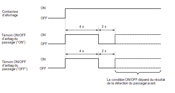
(2) The passenger airbag ON/OFF indicator light comes on for approximately 4 seconds, then turns off for approximately 2 seconds.
(3) Approximately 6 seconds after the ignition switch is turned ON, the passenger airbag ON/OFF indicator light shows ON or OFF depending on the following conditions.
Warning Light OperationFront Passenger Seat Status | Passenger Airbag ON/OFF Indicator | SRS warning light |
|
|---|---|---|---|
ON indicator light | OFF indicator light |
||
Unoccupied |
OFF |
ON |
OFF |
Adult*1 occupies seat |
ON |
OFF |
OFF |
Child*2 occupies seat |
ON or OFF*2 |
OFF or ON*2 |
OFF |
Child restraint system is installed |
OFF |
ON |
OFF |
Occupant classification system malfunction |
OFF |
ON |
ON |
- *1: The system detects a person of adult weight or an adult. If a smaller adult sits in the front passenger seat, the system may not recognize them as an adult, depending on their posture and physique.
- *2: The system may not recognize a child in a child restraint system depending on factors such as the position of the child restraint system or the position and physique of the child.
HINT:
- The passenger airbag ON/OFF indicator light comes on according to the timing chart below to check the indicator light circuit.
- If the occupant classification system malfunctions, the SRS warning light and the passenger airbag ON/OFF indicator light ("OFF") come on. In this case, perform troubleshooting for the SRS airbag system DTCs first.
PASSENGER AIRBAG ON/OFF INDICATOR LIGHT CHECK
(a) Turn the ignition switch to ON.
(b) Check that the passenger airbag ON/OFF indicator light ("ON" and "OFF") comes on for approximately 4 seconds, then turns off for approximately 2 seconds.
HINT:
Refer to the passenger airbag ON/OFF indicator light operation table for the passenger airbag ON/OFF indicator light operation when the ignition switch is turned ON and approximately 6 seconds have elapsed.
SRS CONNECTOR FUNCTIONS
(a) The SRS connectors are arranged as shown in the diagram.
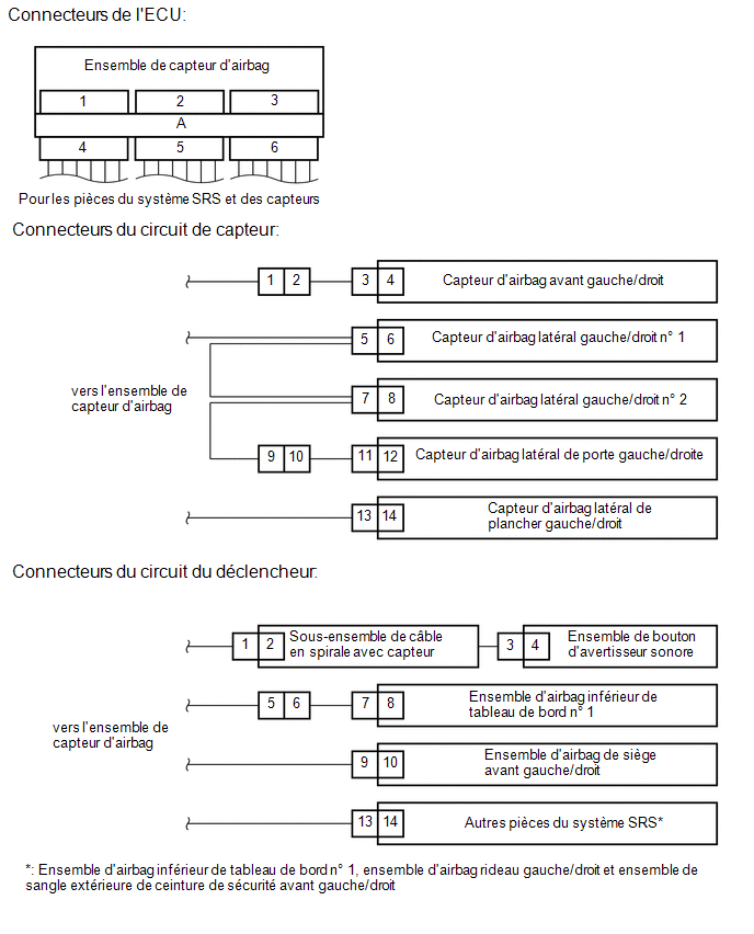
Connector Type | Application |
||
|---|---|---|---|
ECU | Sensor circuit | Squib circuit |
|
Terminal double lock mechanism |
Connectors 4, 5, 6 |
Connectors 1, 9, 10 |
Connectors 1, 5, 6 |
Partial fitting prevention mechanism |
- |
- |
Connectors 1, 5, 11 |
Short-circuit mechanism |
Connectors 4, 5, 6 |
- |
Connectors 2, 4, 6, 8, 10, 12, 14 |
Connector lock mechanism (1) |
- |
- |
Connectors 3, 7, 13 |
Connector position assurance mechanism |
- |
Connectors 2, 3, 5, 7, 11, 13 |
Connector 9 |
Connector lock mechanism (2) |
Connector A |
- |
- |
Incorrect connection prevention lock mechanism |
Connector A |
- |
- |
(b) Terminal double lock mechanism
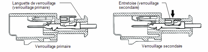
(1) This mechanism is designed to increase the terminal's retention and prevent accidental disconnection.
(2) The connector is made of two parts, the housing and the retainer, to properly lock the terminal using the lock tab (primary lock) and the retainer (secondary lock).
(c) Partial fitting prevention mechanism
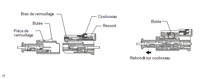
(1) This mechanism is designed to prevent the connector from being only partially connected.
(2) If the connector is not fully connected, the spring disconnects it, resulting in loss of continuity.
(d) Short-circuit mechanism
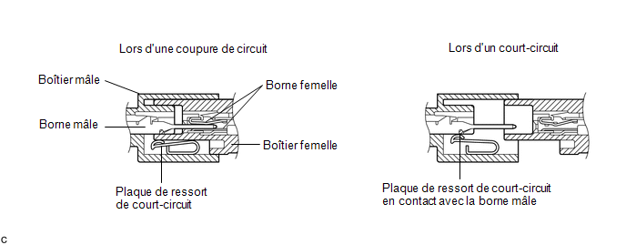
(1) The short-circuit mechanism is designed to automatically short-circuit the positive and negative terminals of an airbag power supply connector when it is disconnected.
(2) The short-circuit spring plate contained in the connector creates a closed circuit on the airbag side (no potential difference can appear between two terminals), which prevents accidental airbag deployment during servicing.
(e) Connector Lock Mechanism (1)
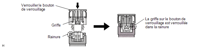
(1) This mechanism is designed to prevent the connector from being accidentally disconnected.
(2) Locking the connector lock button engages the lock button claw in the grooves on the other side of the connector, to ensure it is connected correctly.
(f) Connector Position Assurance (CPA) Mechanism
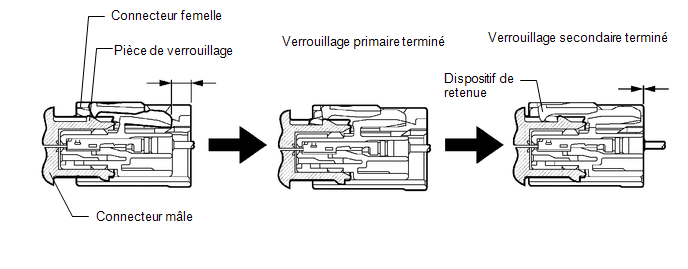
(1) This mechanism is designed to detect when the connector is only partially connected.
(2) The CPA and the female connector slide toward the male connector side simultaneously, and the primary lock is completed when the female connector is engaged with the male connector. From this position, only the CPA slides toward the male connector side, and the secondary lock is completed when the CPA retainer engages the female connector. When the ends of the CPA and the female connector are aligned, they are fully engaged.
(g) Connector Lock Mechanism (2)
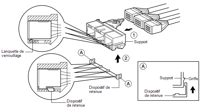
(1) This mechanism is designed to prevent the connector from being accidentally disconnected.
(2) Sliding the connector fully into the holder and locking the lock tab completes the primary lock.
(3) Engaging the retainer on the holder as shown in the illustration completes the secondary lock, which prevents the connector from being accidentally disconnected.
(h) Misconnection Prevention Lock Mechanism
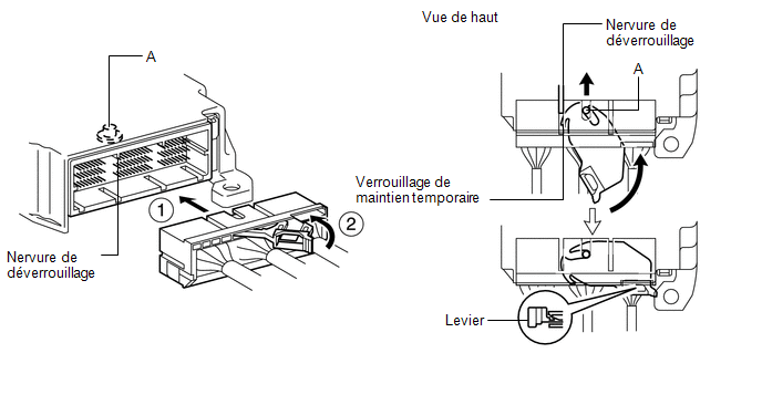
(1) This mechanism is designed to prevent the connector from being only partially connected.
(2) When the holder is connected to the airbag sensor assembly, the release rib releases the temporary hold lock, allowing the lever to be pushed by turning it around axis A.
(3) Locking the lever on the holder properly locks the holder.
ACTIVATION PREVENTION MECHANISM
(a) Function of the Activation Prevention Mechanism
(1) An activation prevention mechanism, designed to prevent accidental activation of the airbag and deployment of the pretensioner, is built into the connector of the airbag squib circuit.
(2) This mechanism closes the circuit when the connector is disconnected, by bringing the short-circuit spring into contact with the terminals, and isolates the circuit from external power sources to prevent accidental activation of the airbag and deployment of the pretensioner.
(b) Releasing the Activation Prevention Mechanism
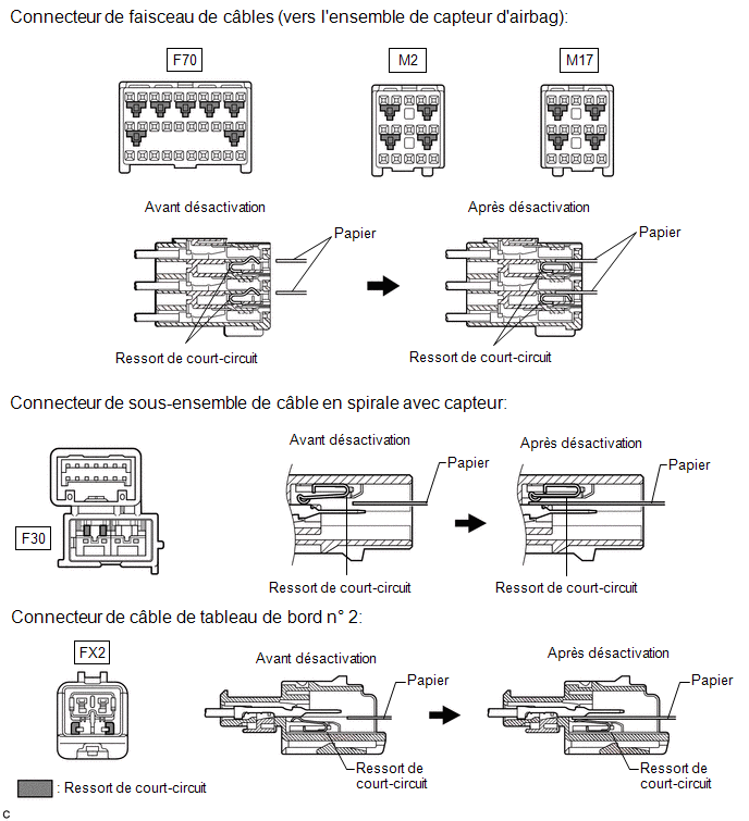
(1) To release the activation prevention mechanism, insert a piece of paper of the same thickness as the male terminal (approximately 0.5 mm (0.0197 in.)) between the terminals and the short-circuit spring to interrupt the connection.
(2) Refer to the following illustration for connectors using the activation prevention mechanism and the release method.
CAUTION:
Never release the activation prevention mechanism at the squib connector, even when inspecting with the squib disconnected.
NOTICE:
- Do not release the activation prevention mechanism unless specifically instructed in the troubleshooting procedure.
- To avoid damaging the terminals and the short-circuit spring, always use a piece of paper of the same thickness as the male terminal.