AAvtotema Toyota Tundra
EN
  • RU
  • EN
  • FR
  • DE
  • IT
  • ES
  1. Home
  2. Toyota
  3. Toyota Tundra
  4. Toyota Tundra Service Manual
  5. Engine, Hybrid System
  6. A760e Automatic Transmission / Transaxle
  7. Automatic Transmission System
  8. System Diagram
Toyota Tundra Service Manual
  • General
  • Audio, Visual, Telematics
  • Brake
  • Engine, Hybrid System
    • 1ur-fe Charging
    • 1ur-fe Cooling
    • 1ur-fe Emission Control
    • 1ur-fe Engine Control
    • 1ur-fe Engine Mechanical
    • 1ur-fe Exhaust
    • 1ur-fe Fuel
    • 1ur-fe Ignition
    • 1ur-fe Intake
    • 1ur-fe Lubrication
    • 1ur-fe Starting
    • A760e Automatic Transmission / Transaxle
      • Automatic Transmission Assembly
      • Automatic Transmission Fluid
      • Automatic Transmission System
        • Check Mode Procedure
        • Data List / Active Test
        • Definition Of Terms
        • Diagnosis System
        • Diagnostic Trouble Code Chart
        • Dtc Check / Clear
        • Fail-safe Chart
        • How To Proceed With Troubleshooting
        • Hydraulic Test
        • Initialization
        • Manual Shifting Test
        • Mechanical System Tests
        • Monitor Drive Pattern
        • Transmission Range Sensor Circuit Malfunction (PRNDL Input) (P0705)
        • Transmission Fluid Temperature Sensor "A" Performance (P0711)
        • Transmission Fluid Temperature Sensor "A" Circuit Low Input (P0712,P0713)
        • Turbine Speed Sensor Circuit No Signal (P0717)
        • Output Speed Sensor Circuit No Signal (P0722)
        • Gear 6 Incorrect Ratio (P0729)
        • Pressure Control Solenoid "A" Electrical (Shift Solenoid Valve SL1) (P0748)
        • Shift Solenoid "A" Performance (Shift Solenoid Valve S1) (P0751)
        • Shift Solenoid "B" Performance (Shift Solenoid Valve S2) (P0756)
        • Shift Solenoid "C" Performance (Shift Solenoid Valve S3) (P0761)
        • Shift Solenoid "D" Performance (Shift Solenoid Valve S4) (P0766,P0776)
        • Pressure Control Solenoid "B" Electrical (Shift Solenoid Valve SL2) (P0778)
        • 1-2 Shift (1-2 Shift Valve) (P0781)
        • Transmission Component Slipping (P0894,P2714)
        • Shift Solenoid "A" Control Circuit Low (Shift Solenoid Valve S1) (P0973,P0974)
        • Shift Solenoid "B" Control Circuit Low (Shift Solenoid Valve S2) (P0976,P0977)
        • Shift Solenoid "C" Control Circuit Low (Shift Solenoid Valve S3) (P0979,P0980)
        • Shift Solenoid "D" Control Circuit Low (Shift Solenoid Valve S4) (P0982,P0983)
        • Shift Solenoid "E" Control Circuit Low (Shift Solenoid Valve SR) (P0985,P0986)
        • Pressure Control Solenoid "D" Electrical (Shift Solenoid Valve SLT) (P2716)
        • Transmission Fluid Temperature Sensor "B" Circuit Low Input (P2742,P2743)
        • Parts Location
        • Precaution
        • Problem Symptoms Table
        • Road Test
        • System Description
        • System Diagram
        • Terminals Of Ecm
        • Transmission Control Switch Circuit
        • Vehicle Control History
      • Automatic Transmission Unit
      • Extension Housing Rear Oil Seal
      • Oil Cooler
      • Oil Pump
      • Park / Neutral Position Switch
      • Shift Lever Assembly(for Column Shift Type)
      • Shift Lever Assembly(for Floor Shift Type)
      • Shift Lock System
      • Speed Sensor
      • Torque Converter Clutch And Drive Plate
      • Transmission Control Cable(for Column Shift Type)
      • Transmission Control Cable(for Floor Shift Type)
      • Transmission Wire
      • Valve Body Assembly
    • Axle
    • Cruise Control
    • Differential
    • Drive Shaft
    • Propeller Shaft
    • Suspension
    • Tire And Wheel
    • Wf1am Transfer
  • Power Source, Network
  • Steering
  • Vehicle Interior
Engine, Hybrid System

System Diagram

In this manual: Engine, Hybrid System
General — 26Audio, Visual, Telematics — 333Brake — 176Engine, Hybrid System — 816Power Source, Network — 88Steering — 88Vehicle Interior — 1071
~1min read

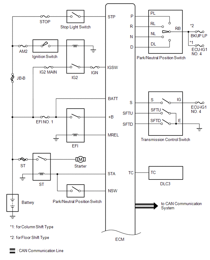
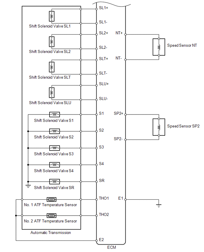
SYSTEM DIAGRAM

The configuration of the electronic control system for the A760E automatic transmission is as shown in the following chart.
← Previous System Description Next → Terminals Of Ecm
Was this page helpful?
© 2026 Avtotema Contact us Privacy policy Cookie settings