Slip Indicator Light Remains ON
The skid control ECU is connected to the combination meter via CAN communication.
The slip indicator light blinks during VSC and/or TRAC operation.
When the system fails, the slip indicator light comes on to warn the driver (See page  ).
WIRING DIAGRAM
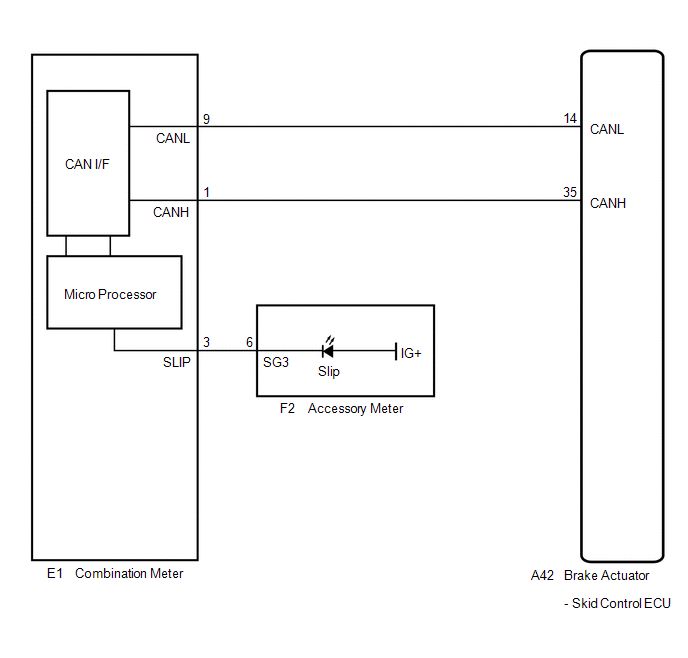
PROCEDURE
CHECK CAN COMMUNICATION SYSTEM
(a) Check if a CAN communication system DTC is output (See page ).
Result | Proceed to |
|---|---|
DTC is not output |
A |
DTC is output |
B |
| B |  | INSPECT CAN COMMUNICATION SYSTEM |
|

CHECK IF SKID CONTROL ECU CONNECTOR IS SECURELY CONNECTED
(a) Check if the skid control ECU connector is securely connected.
OK:
The connector is securely connected.
| NG | | CONNECT CONNECTOR TO ECU CORRECTLY |
|
CHECK BATTERY
(a) Check the battery voltage.
Standard voltage:
11 to 14 V
Result | Proceed to |
|---|---|
OK |
A |
NG (for 2GR-FE) |
B |
NG (for 1AR-FE) |
C |
| B | | CHECK OR REPLACE CHARGING SYSTEM OR BATTERY (for 2GR-FE) |
| C | | CHECK OR REPLACE CHARGING SYSTEM OR BATTERY (for 1AR-FE) |
|
INSPECT COMBINATION METER ASSEMBLY
(a) Turn the ignition switch to ON and check the slip indicator light will come on for approximately 3 seconds (initial check).
(b) Perform the Active Test of the combination meter (meter CPU) using the Techstream (See page ).
(c) Check the accessory meter.
Result | Proceed to |
|---|---|
OK |
A |
NG (Initial check is normal, and the slip indicator light does not turn on or off in accordance with the Techstream operation) |
B |
NG (Initial check is abnormal) |
C |
HINT:
If troubleshooting has been carried out according to Problem Symptoms Table, refer back to the table and proceed to the next step before replacing the part (See page ).
| A | | REPLACE BRAKE ACTUATOR ASSEMBLY |
| B | | REPLACE COMBINATION METER ASSEMBLY |
| C | | REPLACE ACCESSORY METER ASSEMBLY |
Test yourself
A quick Toyota Venza quiz: every answer comes with an explanation and a link to the manual page.