Thermostat
PROCEDURE
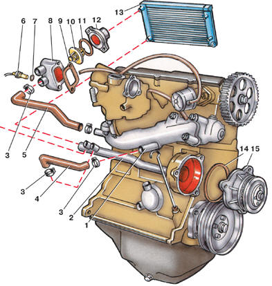
Cooling system components of engines with 1.1 and 1.3 L displacement 1 – inlet pipe connection; 2 – drain tube; 3 – clamp; 4 – hose for draining coolant from the inlet pipe; 5 – hose supplying coolant to the inlet pipe; 6 – coolant temperature sensor; 7 – O-ring; 8 – thermostat housing; 9 – gasket; 10 – thermostat; 11 – O-ring; 12 – thermostat housing cover; 13 – radiator; 14 – O-ring; 15 – water pump
On engines with 1.1 and 1.3 L displacement, the thermostat is installed in housing 8 (see fig.
Cooling system components of engines with 1.1 and 1.3 L displacement) of the thermostat housing, and on engines with 1.6 and 1.8 L displacement in the lower part of housing 13 (see fig. Cooling system components of engines with 1.6 and 1.8 L displacement) of the water pump. Removal and Installation PROCEDURE 1. Drain the coolant from the engine cooling system. 2. On engines with 1.1 and 1.3 L displacement, disconnect hose 12 (see fig. Radiator and cooling fan of engines with 1.1 and 1.3 L displacement) from cover 12 (see fig. Cooling system components of engines with 1.1 and 1.3 L displacement). Unscrew the cover mounting bolts and remove cover 12 with O-ring 11. Remove thermostat 10. 3. On engines with 1.6 and 1.8 L displacement, disconnect hose 18 (see fig. Radiator and cooling fan of engines with 1.6 and 1.8 L displacement) from cover 5 (see fig. Cooling system components of engines with 1.6 and 1.8 L displacement).
Unscrew bolts 6 and remove cover 5 with O-ring 7. Remove thermostat 8. 4. Check the thermostat. To do this, measure the thermostat length as described in step 5. Suspend the thermostat in a container of water heated to 70–75° C so that it does not touch the walls. Gradually heat the water in the container, stirring constantly so that the water temperature is the same throughout the volume. At 88° C the thermostat valve must begin to open. Heat the thermostat to 102° C; at this temperature the thermostat valve must fully open.
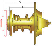
5. Measure the thermostat length in the heated state (A). Its length must increase by 7 mm. Let the thermostat cool and measure its length in the cold state (a). It must be the same as before heating. If these conditions are not met, the thermostat is faulty and must be replaced. 6. Install the thermostat in the reverse order of removal. When installing, replace the O-ring. Tighten the thermostat housing cover bolts to a torque of 10 N·m.
Test yourself
A quick Volkswagen Golf quiz: every answer comes with an explanation and a link to the manual page.