Replacement of Brake Pads (Rear Disc Brake)
PROCEDURE
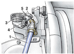
Removal of Parking Brake Cable 1 – cable; 2 – lever; 3 – spring; 4 – bolt; 5 – spring clip
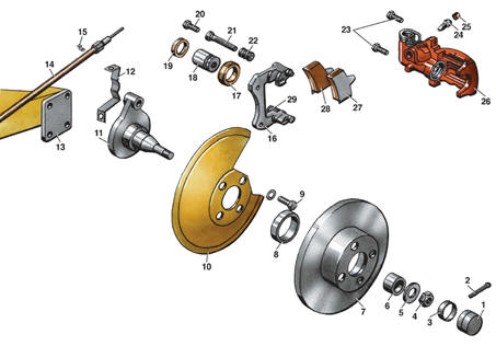
Rear Disc Brake 1 – cap; 2 – cotter pin; 3 – toothed washer; 4 – nut; 5 – washer; 6 – bearing; 7 – brake disc; 8 – sleeve; 9 – bolt; 10 – protective cover; 11 – hub; 12 – bracket; 13 – beam; 14 – parking brake cable; 15 – fastener; 16 – caliper; 17 – protective boot; 18 – piston; 19 – seal; 20 – bolt; 21 – guide pin; 22 – sleeve; 23 – bolt; 24 – bleeder valve; 25 – cap; 26 – cylinder body; 27 – outer brake pad; 28 – inner brake pad; 29 – bolt
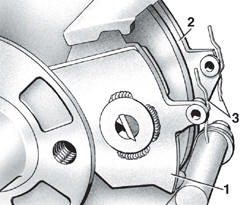
Installation of Brake Pads 1 – outer brake pad; 2 – inner brake pad; 3 – retaining spring
PROCEDURE 1. Place wheel chocks under the front wheels. 2. Loosen the rear wheel bolts. 3. Raise the rear of the vehicle and support it on stands. 4. Remove the rear wheels. 5. Wash the brakes with warm water and dry them. 6. Disconnect parking brake cable 1 (refer to Parking Brake Cable Removal illustration) from lever 2. 7. Remove upper bolt 20 (refer to Rear Disc Brake illustration) securing cylinder body 26 to caliper 16, holding guide pin 21 with a wrench. 8. Loosen lower bolt 29. 9. Rotate cylinder body 26 around lower bolt 29 to gain free access to the brake pads. 10. Mark brake pads 27 and 28 (if the old pads will be reinstalled). 11. Remove brake pads 27 and 28. 12. Check the thickness of the brake pads. The friction material thickness must be at least 7 mm. Otherwise, replace the brake pads together with the friction material. 13. Clean the brake pad seating surfaces with alcohol. 14. Install brake pads 1 and 2 (refer to Brake Pad Installation illustration), making sure retaining springs 3 are in the upper position and parallel to the end face of the pads. 15. Rotate cylinder body 26 (refer to Rear Disc Brake illustration) back into place. 16. Install the old upper bolt 20. 17. Replace lower bolt 29 with a new one. WARNING: The clearance between the outer brake pad and the caliper projections must be 1 mm. Check the clearance with a feeler gauge and adjust if necessary.
18. Using a feeler gauge, check the clearance between outer brake pad 27 and the projections of cylinder housing 26. 19. If the clearance is 1 mm, install new upper bolt 20 and tighten both bolts 20 and 29 to 35 N·m. 20. If the clearance differs from the specified value, unscrew upper bolt 20 and adjust the position of piston 18 by turning it with a hex key until the required clearance is obtained. 21. Install new upper bolt 20 and tighten bolts 20 and 29 to 35 N·m. 22. Secure the parking brake cable (see illustration Parking Brake Cable Removal) to lever 2. 23. Adjust the parking brake (see Subsection 10.12).
Test yourself
A quick Volkswagen Golf quiz: every answer comes with an explanation and a link to the manual page.