Front Brake
PROCEDURE
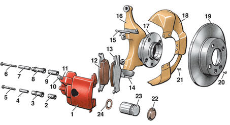
Front wheel brake 1 – caliper; 2, 9 – bushings; 3, 8 – shims; 4, 7 – bushings; 5, 6 – bolts; 10 – cap; 11 – bleed valve; 12 – inner brake pad; 13 – outer brake pad; 14, 15 – clips; 16 – steering knuckle; 17 – hub; 18 – dust cover; 19 – brake disc; 20 – screw; 21 – bolt; 22 – protective cap; 23 – piston; 24 – seal
Removal PROCEDURE 1. Apply the parking brake. 2. Place wheel chocks under the rear wheels. 3. Loosen the wheel bolts. 4. Raise the front of the vehicle and support it on stands. 5. Remove the wheels. 6. Clean the brakes with warm water and dry them. Warning: Do not use gasoline, diesel fuel or any other mineral solvents to clean the brakes.
7. Loosen the lock nut of the brake hose fitting on caliper 1 by half a turn (see fig. Front Wheel Brake), then retighten it without fully tightening, to ease further removal. 8. Remove cap 10 from bleed valve 11. 9. Unscrew the upper 6 and lower 5 caliper mounting bolts from steering knuckle 16. 10. Note the position of bushings 4 and 7 and remove them. 11. Remove caliper 1, first pulling out its lower part. 12. Hang the caliper on wire from the body, making sure it does not hang down or twist the brake hoses. 13. Mark brake pads 12 and 13 as installed. Warning: Do not interchange the inner and outer pads with each other, or between the left and right wheels. This may cause uneven braking.
14. Remove brake pads 12 and 13 and clips 14 and 15. 15. Clean brake disc 19 of dirt and rust (do not touch its working surface). 16. Place a container under caliper 1. 17. Disconnect the brake hose fittings from the caliper and plug the brake hose openings. 18. Unscrew bleed valve 11 from caliper 1. 19. Remove protective cap 22 from piston 23. 20. Remove piston 23 by clamping the seat of the protective cap with pliers. Warning: If the piston is difficult to remove from the cylinder, reinstall bleed valve 11 and the brake hoses, then push the piston out by pressing the brake pedal. To remove the seal, use a wooden or plastic spatula.
Use of metal tools is not recommended, as the inner surface of the cylinder may be damaged.
21. Remove seal 24. 22. Wash all parts with water and detergent and dry them. 23. Inspect the working surfaces of piston 23 and the cylinder. Warning: If wear, seizure or gouges are found on the working surfaces of the piston or cylinder, replace the piston and caliper as a set.
Checking the Condition of Brake Disc Working Surfaces Warning: Checking the condition of brake disc working surfaces is performed without removing the disc from the vehicle.
PROCEDURE 1. Clean brake disc 19 (see fig. Front Wheel Brake). 2. Measure disc thickness with a micrometer (for values, see subsection 10.1). Warning: If disc thickness is less than the minimum or groove depth exceeds the permissible value, replace the disc. If grooves are shallow, the disc can be removed and resurfaced, but its final thickness must not be less than the minimum.
3. Check runout of brake disc working surfaces relative to the plane of rotation (for values, see subsection 10.1). Warning: If runout exceeds the permissible value, remove the disc and resurface it, making sure its final thickness is not less than the minimum. Otherwise, replace the disc.
Removal of Brake Disc PROCEDURE 1. Remove screw 20. 2. Remove brake disc 19. 3. Remove bolts 21. 4. Remove protective cover 18. Installation of Brake Disc Install the brake disc in the reverse order of removal. Before installation, clean the mating surfaces of the wheel hub and the brake disc. PROCEDURE WARNING: Seal 24 (refer to Front Wheel Brake illustration) and protective boot 22 of piston 23 must be replaced.
1. Lubricate the inner surface of the cylinder with brake fluid. 2. Lubricate new seal 24 with brake fluid and insert it into the cylinder bore. 3. Lubricate new protective boot 22 with brake fluid and install it on piston 23. 4. Insert piston 23 into the cylinder by hand, without using any tool. 5. Install bleeder valve 11. 6. Remove the plug from the brake hose and connect the brake hose to caliper 1, but do not tighten the hose end lock nut. 7. Install retainers 14 and 15. 8. Install brake pads 12 and 13 in accordance with the previously made marks. 9. Install the caliper on steering knuckle 16, starting from the top and then rotating downward. 10. Install upper bolt 6 together with sleeve 7. 11. Install lower bolt 5 together with sleeve 4. 12. Tighten bolts 5 and 6 to a torque of 40 N·m. 13. Tighten the brake hose end lock nut, making sure the hoses are not twisted. 14. Bleed the brake system, starting with air bleeding from the installed caliper.
Test yourself
A quick Volkswagen Golf quiz: every answer comes with an explanation and a link to the manual page.