Flushing (cleaning) refrigerant circuit with refrigerant R134a
Vehicles with high-voltage system (hybrid vehicles)
For all work on vehicles with a high-voltage system, observe the additional warnings for these vehicles → Electrical system.

WARNING!
Danger from unexpected engine start
For general work on high-voltage vehicles, switch off the ignition and place the ignition key outside the passenger compartment.

WARNING!
Handling high-voltage cables:
- Do not lean on high-voltage cables or their components, and do not rest tools on them --> damage to insulation.
- High-voltage cables must not be bent sharply or kinked --> damage to insulation.
- The round high-voltage connectors are colour-coded by an outer colour ring and mechanically coded by guide or coding lugs. This coding must be observed when mating the round high-voltage connectors to avoid mechanical damage to the high-voltage connectors.

DANGER!
Life-threatening voltage if high-voltage components are damaged
When working near high-voltage components and high-voltage cables, observe the following:
- Cutting, forming or sharp-edged tools, and heat sources such as welding, soldering, hot air or thermal bonding, are prohibited.
- Carry out a visual inspection of the high-voltage components in the work area before starting work on them.
- When working in the engine compartment, visually inspect the power and control electronics for electric drive -JX1-, the electric drive motor -V141-, the A/C compressor -V470- and the high-voltage cables.
- When working on the underbody, visually inspect the high-voltage cables and covers.
- When working in the rear area, visually inspect the high-voltage cables and the electrical box with the service plug for high-voltage system -TW-.
- Visually inspect all equipotential bonding cables.
The following points must be observed during the visual inspection:
- All components must be free of external damage.
- The insulation of the high-voltage cables and equipotential bonding cables must not be damaged.
- The high-voltage cables must not show any unusual deformation.
- Each high-voltage component must be marked with a red warning label.
If work near high-voltage system components is necessary, carry out a visual inspection for damage to the high-voltage components and cables, and observe "General warnings for work on the high-voltage system" → Electrical system.
If work on high-voltage system components is necessary, establish that the high-voltage system is de-energised → Electrical system, and observe "General warnings for work on the high-voltage system" → Electrical system.

Caution!
- If there is a suspicion that chemical substances for sealing leaks have been added to the vehicle's refrigerant circuit, do not connect the air conditioning service unit and do not extract the refrigerant.
- Chemical leak sealants form deposits in the refrigerant circuit that impair the function of the air conditioning system and lead to failure of the air conditioning system (and your air conditioning service unit).
- Inform the customer that the refrigerant circuit contains substances not approved by VW, so this refrigerant circuit cannot be flushed. Repair of the refrigerant circuit is therefore only possible by replacing all components that have come into contact with this substance.

Note
- VW does not permit the use of chemical substances to seal leaks in the refrigerant circuit.
- Chemical substances for sealing leaks in the refrigerant circuit mostly react with the ambient air and the humidity it contains. They cause deposits in the refrigerant circuit (and in your A/C service station), leading to malfunctions in valves and other components they come into contact with. These deposits cannot be completely removed from the components (even by flushing). Repair of the refrigerant circuit is therefore only possible by replacing all components that have come into contact with this substance.
- Chemical sealants for leaks in the refrigerant circuit usually cannot be identified from the outside. The required label that must be affixed to mark their use is usually not present. For this reason, be cautious with a vehicle whose history you do not know.
- To remove contaminants (e.g. abrasion from a defective A/C compressor) and aged refrigerant oil as cleanly as possible and with little work, the refrigerant circuit must be flushed with refrigerant R134a.
On vehicles with an electrically driven A/C compressor, observe the notes on replacing the electric A/C compressor -V470-. If the A/C compressor electronics are damaged, the refrigerant circuit does not always need to be cleaned.
The refrigerant circuit must be flushed with refrigerant R134a if:
- there is dirt or other contamination in the refrigerant circuit.
- the vacuum gauge reading does not hold when evacuating a sealed refrigerant circuit (moisture is in the refrigerant circuit and builds up pressure).
- the refrigerant circuit was open for longer than the normal installation time (e.g. after an accident).
- pressure and temperature measurements in the refrigerant circuit indicate that moisture is present in the refrigerant circuit.
- the refrigerant oil quantity in the refrigerant circuit is unknown. If the A/C compressor is to be reinstalled in this case, drain the refrigerant oil from the A/C compressor via the oil drain plug. To make this easier, turn the V-ribbed belt pulley or clutch plate of the magnetic clutch on the A/C compressor by hand. After flushing, add the total refrigerant oil quantity to the refrigerant circuit according to → Vehicle-specific repair manual (50 grams directly into the A/C compressor). Observe the additional oil quantity for systems with a second evaporator.
- the A/C compressor had to be replaced due to internal damage (e.g. noises or no cooling performance).
- the vehicle-specific repair manual requires it after replacing certain components.
- a different A/C compressor with different refrigerant oil is to be installed.
Required tools
- A/C service station with flushing unit -VAS 6381- or A/C service station with flushing unit -VAS 6337-. These A/C service stations include the additional function "Flush refrigerant circuit with refrigerant R134a" and the flushing device for refrigerant circuits required for it → Catalog of Workshop Equipment and Special Tools.
- Adapter case PKW set VW/Audi -VAS 6338/1- and → Catalog of Workshop Equipment and Special Tools.
- Adapter case NFZ set -VAS 6338/50- and → Catalog of Workshop Equipment and Special Tools.

Note
- If your workshop does not have either of the two A/C service stations listed above, you can also flush the refrigerant circuit with the flushing device for refrigerant circuits -VAS 6336/1- or flushing device for refrigerant circuits -VAS 6337/1-, depending on the version of your A/C service station (minimum 7 kg of refrigerant R134a in the refrigerant cylinder). The flushing cycle must then be carried out manually.
- On vehicles with screw connections on the refrigerant circuit, adapters -V.A.G 1785/1- through -V.A.G 1785/8- from the adapter case PKW set VW/Audi -VAS 6338/1- or adapter case NFZ set -VAS 6338/50- can be used. On vehicles with screw connections on the A/C compressor and on the accumulator, adapter -V.A.G 1785/8- is required twice.
- The adapter cases also contain a filling hose -VAS 6338/31- with 5/8-18 UNF connections and a large inside diameter for bridging components (it is commercially available).
Preliminary work
- Evacuate the refrigerant circuit.
- Remove the A/C compressor → Heating, Air Conditioning.
On a vehicle with an orifice tube and accumulator.
- Remove the orifice tube (vehicle-specific) and reconnect the refrigerant lines → Heating, Air Conditioning.
- Remove the accumulator (vehicle-specific) → Heating, Air Conditioning and connect the refrigerant lines together (use the adapters and the filling hose -VAS 6338/31-) from the adapter case PKW set VW/Audi -VAS 6338/1-.

Note
The accumulator could be flushed, but because of its large internal volume it holds too much liquid refrigerant. When this refrigerant is extracted, the accumulator freezes heavily and the extraction process takes too long.
On a vehicle with an expansion valve and receiver-drier.
- Remove the receiver-drier → Heating, Air Conditioning (vehicle-specific, not necessary on all vehicles) and connect the refrigerant lines together (use the adapters and the filling hose -VAS 6338/31-).
- Remove the expansion valve → Heating, Air Conditioning (vehicle-specific) and insert an adapter for it.

Note
If no suitable adapter for the expansion valve is available in the adapter case PKW set VW/Audi -VAS 6338/1- or adapter case NFZ set -VAS 6338/50-, the removed expansion valve can be drilled out (the old expansion valve must be replaced with a new one).

Caution!
- When drilling out, make sure the sealing surfaces on the expansion valve are not damaged.
- Otherwise refrigerant will leak out.

Note
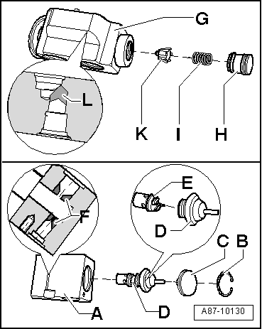
- Before drilling out, some parts must be removed from the expansion valve.
- Expansion valves are available in different versions. For version -A-, remove parts -B-, -C- and -D-. Then separate control element -E- from part -D-. Next, drill out the expansion valve in area -F- with a suitable drill bit (diameter 6 mm).
- For version -G-, remove parts -H-, -I- and -K-, then drill out area -L- with a suitable drill bit (diameter 6 mm).
- Clean the drilled-out expansion valve of machining debris (chips).
- Reinstall parts -B-, -C- and -D- for version -A-, or part -H- for version -G-.

Note
On vehicles with two evaporators, the circuit to the second evaporator must be separated from the circuit of the first evaporator and flushed in a separate operation → Heating, Air Conditioning.
Drilling out the shut-off valve.

Note
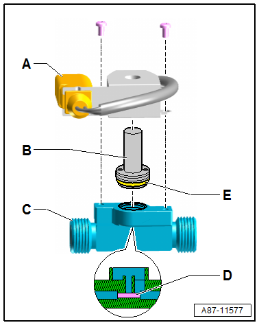
- Two shut-off valves are required to flush the refrigerant circuit. One shut-off valve must be drilled out, for example, if no shut-off valve -VAS 6338/42- is available for flushing the refrigerant circuit.
- Before drilling out, remove the solenoid coil -A- and the solenoid valve -B-.
- Drill out the shut-off valve -C- with a suitable drill bit (drill diameter, for example, 5.0 mm).
- Clean the shut-off valve -C- to remove the chips produced when drilling the bore -D-.
- Reinstall the solenoid valve -B- with the associated seal -E- in the enlarged shut-off valve -C-.
Flushing
- Check the refrigerant quantity in the refrigerant cylinder. There must be at least 7 kg of R134a refrigerant.

Note
If necessary, switch on the heater fitted to your refrigerant cylinder 30 minutes before the first flush. This increases the pressure in the refrigerant cylinder and speeds up filling of the flushing circuit.
- Empty the waste oil container of the A/C service station.
- Connect the supply hose (high-pressure side) of the A/C service station to the low-pressure line to the A/C compressor using an adapter (line with the larger diameter).
- Connect the return hose (low-pressure or suction side) of the A/C service station to the outlet of the refrigerant circuit flushing device.
- Connect the inlet of the refrigerant circuit flushing device to the high-pressure line to the A/C compressor using an adapter (line with the smaller diameter).

Note
- The components are always flushed (except for the electrically driven A/C compressor) against the direction of refrigerant flow during A/C operation.
- During flushing, contaminants from the refrigerant circuit pass into the refrigerant circuit flushing device and the A/C service station, where they are retained by the filters and desiccant installed there. Depending on the contamination, these components must be replaced at shorter intervals in accordance with the operating instructions of the A/C service station or the refrigerant circuit flushing device.
- Depending on the type and severity of contamination of the flushed refrigerant circuits, the filter in the refrigerant circuit flushing device must be replaced after 2 flushing cycles at the latest (flushed vehicles). If a heavily contaminated refrigerant circuit is flushed (the refrigerant oil from the refrigerant circuit is black and viscous, or there are many chips in the refrigerant circuit), the filter must be replaced after flushing the refrigerant circuit. For such heavily contaminated refrigerant circuits, it is also advisable to flush the refrigerant circuit again after replacing the filter.
- Depending on the type of contamination, dirt (old refrigerant oil and abrasion from the A/C compressor) deposits on the sight glass or glasses of the refrigerant circuit flushing device. Clean the sight glass or glasses after flushing, then flush the refrigerant circuit once more in a flushing process to check.
- Liquid refrigerant cannot be routed through the expansion valve, the orifice tube and the receiver-drier desiccant bag of certain liquid tanks at the required speed. These components must therefore be removed and replaced with adapters → Heating, Air Conditioning.
- Adapter for connecting the A/C service station and for bypassing certain components in the refrigerant circuit.
- Switch on the A/C service station and flush the refrigerant circuit (duration approx. 1 to 1.5 hours for one flushing cycle with three flushing processes of approx. 4 kg R134a refrigerant each).

Note
- Flush the refrigerant circuit in accordance with the operating instructions of the A/C service station.
- Depending on the design of the A/C service station, the waste oil container holds only approx. 125 cm3 of refrigerant oil. If a system with a larger amount of refrigerant oil must be flushed, it may be necessary to empty the waste oil container after the first flushing process of a flushing cycle.
- Observe the refrigerant flowing back from the refrigerant circuit. The refrigerant circuit is clean only when the refrigerant flows clear and completely colorless through the sight glass or glasses of the refrigerant circuit flushing device into the A/C service station.
- During flushing, all of the refrigerant oil is washed out of the refrigerant circuit, except for minimal residues, which can be disregarded.
- For particularly heavy contamination, it may be necessary to carry out the flushing cycle twice (two flushing cycles with three flushing processes each). Before the second flushing cycle, the filter in the flushing device must be replaced with a new one.
Flushing sequence (the sequence runs automatically according to the program of the A/C service station)
- After switching on, the flushing circuit (refrigerant circuit with connecting hoses and the refrigerant circuit flushing device) is first evacuated, and the refrigerant circuit is checked for leaks during this process. Depending on the design of the A/C service station, manual advancement to the next step may be necessary.
- A specified quantity of refrigerant is charged into the evacuated flushing circuit via the high-pressure side of the A/C service station (opposite to the normal flow direction during A/C operation and thus on the low-pressure side of the vehicle refrigerant circuit), e.g. 4 kg. Depending on the design of the A/C service station, refrigerant is charged until the flushing circuit is completely filled with liquid refrigerant. This is detected when, for example, no more refrigerant flows in for a certain period of time.
- After the specified quantity of refrigerant has been charged, depending on the design of the A/C service station and the refrigerant circuit flushing device, the heater of the refrigerant circuit flushing device is switched on, for example (only if the refrigerant is drawn out of the refrigerant circuit flushing device in gaseous form).
- After the refrigerant has been extracted, switch off the heater of the flushing device (if fitted) for refrigerant circuits. Depending on the version, the refrigerant circuit may be evacuated briefly again. After evacuation, the refrigerant oil extracted from the refrigerant circuit is separated by the air conditioning service station.
- The sequence of refilling refrigerant, extracting (and evacuating) is repeated twice (three times in total).
- After the third extraction, depending on the version of the air conditioning service station, evacuate the flushing circuit.
- After the flushing cycle has finished, check the sight glass or glasses of the flushing device for refrigerant circuits. If they are dirty, clean them according to the operating instructions of the flushing device for refrigerant circuits or the air conditioning service station. Repeat the flushing cycle as a check. One flushing process is sufficient (approx. 30 min.).
- Check the pressure in the refrigerant circuit. There must be no overpressure in the refrigerant circuit (if necessary, briefly evacuate the refrigerant circuit again).
- Disconnect the connections to the air conditioning service station from the vehicle's refrigerant circuit. There must be no overpressure in the refrigerant circuit.
- Replace these components as specified for the vehicle.
- Restrictor and accumulator
- Expansion valve and liquid reservoir or drier cartridge in the liquid reservoir
- Depending on the complaint, replace the A/C compressor → Heating, Air Conditioning and → Parts Catalogue, or drain the remaining refrigerant oil from the removed A/C compressor (replace refrigerant circuit components) and refill the specified quantity of fresh refrigerant oil → Vehicle-specific Repair Manual.

Note
- The original A/C compressor part contains a specified quantity of refrigerant oil. On vehicles with two evaporators, you may need to add an additional specified quantity of refrigerant oil to the circuit → Vehicle-specific Repair Manual.
- If the A/C compressor is not to be replaced, top up the refrigerant oil quantity in the A/C compressor according to the specified fill quantity (pour out the refrigerant oil and reintroduce the specified quantity into the A/C compressor or the refrigerant circuit) (replace refrigerant circuit components) and → Vehicle-specific Repair Manual.
- Reassemble the refrigerant circuit completely → Heating, Air Conditioning.
- Evacuate and charge the refrigerant circuit according to specifications.
- Put the air conditioning system into operation as specified → Heating, Air Conditioning.
Schematic diagrams for the various flushing circuits

Note
- The arrows in the following illustrations show the direction of refrigerant flow during flushing. During flushing, the refrigerant flows opposite to the direction of flow in air conditioning operation, so the high-pressure side of the air conditioning service station is connected to the low-pressure connection of the refrigerant circuit leading to the A/C compressor.
- These schematic diagrams show a refrigerant circuit with a restrictor and accumulator, and a refrigerant circuit with an expansion valve, liquid reservoir and a second evaporator (additional equipment on certain vehicles).
- Depending on the design of the air conditioning service station, non-return valves may be fitted between the refrigerant circuit and the air conditioning service station. These ensure the correct direction of refrigerant flow during flushing.
Refrigerant circuit with orifice tube and accumulator

Note
On vehicles with a restrictor and accumulator, remove the restrictor and the accumulator. Reconnect the refrigerant lines of the restrictor. Connect the refrigerant lines to the removed accumulator using two adapters and the filling hose -VAS 6338/31- (from the adapter case PKW-Set VW/Audi -VAS 6338/1-).
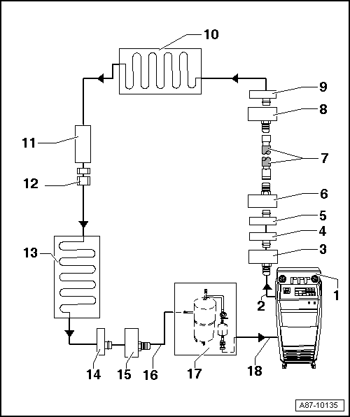
- Air conditioning service station
- With electronics and a flushing program, e.g. air conditioning service station -VAS 6380- with flushing device, or air conditioning service station with flushing device -VAS 6337-.
- If an air conditioning service station without a flushing program is used, the procedure must be carried out manually (evacuate, flush 3 times with at least 4 kg of refrigerant each time and extract the refrigerant again, evacuate).
- Refrigerant hose of the air conditioning service station
- From the high-pressure side of the air conditioning service station (usually colored red) to the connection for the low-pressure side of the A/C compressor on the refrigerant circuit (larger diameter).
- Adapter for connection to the low-pressure side of the refrigerant circuit
- Different versions depending on the vehicle.
- From the adapter case PKW-Set VW/Audi -VAS 6338/1-.
- Low-pressure side connection on the refrigerant circuit
- Different versions depending on the vehicle.
- On the refrigerant line from the A/C compressor to the accumulator.
- Connection to the accumulator
- Different versions depending on the vehicle.
- On the refrigerant line from the A/C compressor to the accumulator.
- Adapter for bridging the removed accumulator
- Different versions depending on the vehicle.
- From the adapter case PKW-Set VW/Audi -VAS 6338/1-.
- Refrigerant filling hose
- For example filling hose -VAS 6338/31- (from the adapter case PKW-Set VW/Audi -VAS 6338/1-).
- Adapter for bridging the removed accumulator
- Different versions depending on the vehicle.
- From the adapter case PKW-Set VW/Audi -VAS 6338/1-.
- Connection to the accumulator
- Different versions depending on the vehicle.
- Evaporator
- Installation location of the restrictor
- The restrictor is removed.
- Remove the restrictor → Heating, Air Conditioning.
- Threaded connection in the refrigerant line
- After removing the restrictor, reconnect the threaded connection → Heating, Air Conditioning.
- Condenser
- High-pressure side connection on the refrigerant circuit
- Different versions depending on the vehicle.
- Adapter for connection to the high-pressure side of the refrigerant circuit
- Different versions depending on the vehicle.
- From the adapter case PKW-Set VW/Audi -VAS 6338/1-.
- Filling hose to the flushing device for refrigerant circuits
- From the connection to the high-pressure side of the A/C compressor on the refrigerant circuit (smaller diameter) to the inlet of the flushing device for refrigerant circuits -VAS 6336/1- or flushing device for refrigerant circuits -VAS 6337/1-.
- Flushing device for refrigerant circuits
- Different versions and designs, e.g. flushing device for refrigerant circuits -VAS 6336/1- or flushing device for refrigerant circuits -VAS 6337/1-.
- With filter, sight glass, safety valve, heater, refrigerant container, etc. (depending on the version).
- Depending on the design of the air conditioning service station and the flushing device for refrigerant circuits, a non-return valve may be installed at the outlet of the flushing device for refrigerant circuits (to ensure the correct flow direction of the refrigerant during flushing).
- Refrigerant hose of the air conditioning service station
- From the low-pressure side of the air conditioning service station (usually colored blue) to the outlet of the flushing device for refrigerant circuits.
Refrigerant circuit with expansion valve, receiver-drier and second evaporator

Note
- This schematic diagram shows a refrigerant circuit with expansion valve, receiver-drier and a second evaporator (additional equipment on certain vehicles).
- On vehicles with an expansion valve and receiver-drier, remove the expansion valve and replace it with an adapter. Depending on the vehicle, either flush the receiver-drier or remove the desiccant cartridge. Depending on the design of the receiver-drier, remove it and connect the line connections to the receiver-drier with two adapters and a filling hose.
- On a vehicle with only one evaporator, the components from item "16" onward are not present or not required.
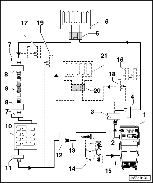
- Air conditioning service station
- With electronics and a flushing program, e.g. air conditioning service station -VAS 6380- with flushing device, or air conditioning service station with flushing device -VAS 6337-.
- If an air conditioning service station without a flushing program is used, the procedure must be carried out manually.
- If present, extract the refrigerant.
- Install the flushing device for refrigerant circuits -VAS 6336/1- or flushing device for refrigerant circuits -VAS 6337/1- between the air conditioning service station and the return line of the refrigerant circuit.
- Evacuate the refrigerant circuit for 20 minutes, then fill it with 4 kg of refrigerant R134a. Then extract again and repeat the process twice more. If the refrigerant in the sight glass/glasses is not clear after the third cycle, another cycle is required.
- Refrigerant hose of the air conditioning service station
- From the high-pressure side of the air conditioning service station (usually colored red) to the connection for the low-pressure side of the A/C compressor on the refrigerant circuit (larger diameter).
- Adapter for connection to the low-pressure side of the refrigerant circuit
- Different versions depending on the vehicle.
- From the adapter case PKW-Set VW/Audi -VAS 6338/1-.
- Low-pressure side connection on the refrigerant circuit
- Different versions depending on the vehicle.
- Adapter for the removed expansion valve
- Different versions depending on the vehicle.
- From the adapter case PKW-Set VW/Audi -VAS 6338/1-.
- Evaporator
- Connection to receiver-drier
- Different versions depending on the vehicle.
- On vehicles with a desiccant cartridge in the receiver-drier on the condenser, or a receiver-drier integrated in the condenser, not present → Heating, Air Conditioning.
- Adapter for bridging the removed receiver-drier
- Not necessary on all vehicles.
- Different versions depending on the vehicle.
- From the adapter case PKW-Set VW/Audi -VAS 6338/1-.
- Refrigerant filling hose
- For example filling hose -VAS 6338/31- (from the adapter case PKW-Set VW/Audi -VAS 6338/1-).
- Condenser
- If the condenser has a receiver-drier with a desiccant cartridge, the desiccant cartridge must be removed (reseal the receiver-drier on or in the condenser after removal) → Heating, Air Conditioning.
- If the receiver-drier is mounted directly on the condenser, the receiver-drier may only be removed and replaced after flushing → Heating, Air Conditioning.
- High-pressure side connection on the refrigerant circuit
- Different versions depending on the vehicle.
- Adapter for connection to the high-pressure side of the refrigerant circuit
- Different versions depending on the vehicle.
- From the adapter case PKW-Set VW/Audi -VAS 6338/1-.
- Filling hose to the flushing device for refrigerant circuits
- From the connection to the high-pressure side of the refrigerant compressor on the refrigerant circuit (smaller diameter) to the inlet of the flushing device for refrigerant circuits.
- Flushing device for refrigerant circuits
- Different versions and designs, e.g. flushing device for refrigerant circuits -VAS 6336/1- or flushing device for refrigerant circuits -VAS 6337/1-.
- With filter, sight glass, safety valve, heater, refrigerant container, etc. (depending on the version).
- Depending on the design of the air conditioning service station and the flushing device for refrigerant circuits, a non-return valve may be installed at the outlet of the flushing device for refrigerant circuits (to ensure the correct flow direction of the refrigerant during flushing).
- Refrigerant hose of the air conditioning service station
- From the low-pressure side of the air conditioning service station (usually colored blue) to the outlet of the flushing device for refrigerant circuits.
- Adapter for sealing the outlet to the second evaporator
- Only necessary on certain vehicles with the "2nd evaporator" additional equipment.
- From the adapter case NFZ-Set -VAS 6338/50-.
- Adapter for sealing the outlet to the second evaporator
- Only necessary on certain vehicles with the "2nd evaporator" additional equipment.
- From the adapter case NFZ-Set -VAS 6338/50-.
- Connection of the low-pressure side on the refrigerant circuit to the second evaporator
- Different versions depending on the vehicle.
- Only present on certain vehicles with the "2nd evaporator" additional equipment.
- Connection of the high-pressure side on the refrigerant circuit to the second evaporator
- Different versions depending on the vehicle.
- Only present on certain vehicles with the "2nd evaporator" additional equipment.
- Adapter for the removed expansion valve on the second evaporator
- Different versions depending on the vehicle.
- Only necessary on certain vehicles with the "2nd evaporator" additional equipment.
- From the adapter case NFZ-Set -VAS 6338/50-.
- Second evaporator
- Only present on certain vehicles with the "2nd evaporator" additional equipment.
Flushing the electrically driven refrigerant compressor
Vehicles with high-voltage system
For all work on vehicles with a high-voltage system, observe the additional warnings for these vehicles → Electrical system.

WARNING!
Danger from unexpected engine start
For general work on high-voltage vehicles, switch off the ignition and place the ignition key outside the passenger compartment.

WARNING!
Handling high-voltage cables:
- Do not lean on high-voltage cables or their components, and do not rest tools on them --> damage to insulation.
- High-voltage cables must not be bent sharply or kinked --> damage to insulation.
- The round high-voltage connectors are colour-coded by an outer colour ring and mechanically coded by guide or coding lugs. This coding must be observed when mating the round high-voltage connectors to avoid mechanical damage to the high-voltage connectors.

DANGER!
Life-threatening voltage if high-voltage components are damaged
When working near high-voltage components and high-voltage cables, observe the following:
- Cutting, forming or sharp-edged tools, and heat sources such as welding, soldering, hot air or thermal bonding, are prohibited.
- Carry out a visual inspection of the high-voltage components in the work area before starting work on them.
- When working in the engine compartment, visually inspect the power and control electronics for electric drive -JX1-, the electric drive motor -V141-, the A/C compressor -V470- and the high-voltage cables.
- When working on the underbody, visually inspect the high-voltage cables and covers.
- When working in the rear area, visually inspect the high-voltage cables and the electrical box with the service plug for high-voltage system -TW-.
- Visually inspect all equipotential bonding cables.
The following points must be observed during the visual inspection:
- All components must be free of external damage.
- The insulation of the high-voltage cables and equipotential bonding cables must not be damaged.
- The high-voltage cables must not show any unusual deformation.
- Each high-voltage component must be marked with a red warning label.
If work near high-voltage system components is necessary, carry out a visual inspection for damage to the high-voltage components and cables, and observe "General warnings for work on the high-voltage system" → Electrical system.
If work on high-voltage system components is required, make the high-voltage system voltage-free → Electrical System and observe "General Warnings for Work on the High-Voltage System" → Electrical System.

Note
The electrically driven refrigerant compressor must be flushed if there is suspicion that there is too much refrigerant oil in the refrigerant circuit, or to remove contaminated (moisture-laden) refrigerant oil from the refrigerant compressor. In these cases, the refrigerant circuit must also be flushed so that it is cleaned and the correct refrigerant oil quantity for the refrigerant circuit can be set again.
If an electrically driven refrigerant compressor is replaced without having a mechanical fault (e.g. defective circuit board), the refrigerant oil quantity must be determined from this refrigerant compressor.

Note
- The refrigerant compressor must be flushed so that the refrigerant oil to be determined is released from this refrigerant compressor.
- The refrigerant compressor is flushed in the direction of flow (from the low-pressure side inlet to the high-pressure side outlet).
- To flush as much refrigerant oil as possible out of the refrigerant compressor, position the refrigerant compressor during flushing so that the high-pressure side outlet is as low as possible.
- If an air conditioning service station without a flushing program is used, the procedure must be carried out manually (evacuate, flush 3 times with at least 2 kg of refrigerant each time and extract the refrigerant again, evacuate).
Determined quantity, e.g. 50 cm³
Then pour out enough refrigerant oil from the new refrigerant compressor so that only the quantity remaining in the new refrigerant compressor (plus 10 cm³) is left, equal to the quantity previously flushed out of the old refrigerant compressor. A new original refrigerant compressor has e.g. 200 cm³, so pour out only 140 cm³.
- Pour out the old refrigerant oil from the refrigerant compressor. For handling refrigerant oil → Volkswagen ServiceNet, HS Environmental Protection, Waste Disposal, Current Status, Disposal Routes, Waste Oil Disposal, Refrigeration Oils.

Note
If not enough refrigerant oil can be poured out of the new refrigerant compressor to be installed, the new refrigerant compressor must be flushed. After flushing, fill the new refrigerant compressor with as much new refrigerant oil as the quantity determined from the compressor being replaced.
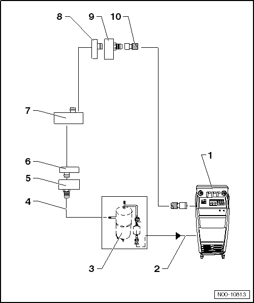
- Air conditioning service station

Note
Flushing of the refrigerant compressor is carried out manually.
- If present, extract the refrigerant.
- Empty the waste oil container of the air conditioning service station.

Note
On some air conditioning service stations, the oil is only separated during the vacuum phase and then filled into the waste oil container.
- Set the refrigerant quantity on the air conditioning service station to 2 kg and the oil quantity to 0.
- Install the flushing device for refrigerant circuits -VAS 6336/1- or flushing device for refrigerant circuits -VAS 6337/1- between the air conditioning service station and the return line of the refrigerant circuit.
- Evacuate the refrigerant circuit for 10 minutes. Then watch the vacuum gauge. If the vacuum holds, charge 2 kg of R134a refrigerant into the circuit. Then evacuate again and repeat the process once more.
- Refrigerant hose of the air conditioning service station
- From the low-pressure side of the air conditioning service station (usually colored blue) to the outlet of the flushing device for refrigerant circuits.
- Flushing device for refrigerant circuits
- Different versions and designs, e.g. flushing device for refrigerant circuits -VAS 6336/1- or flushing device for refrigerant circuits -VAS 6337/1-.
- With filter, sight glass, safety valve, heater, refrigerant container, etc. (depending on the version).
- Depending on the design of the air conditioning service station and the flushing device for refrigerant circuits, a non-return valve may be installed at the outlet of the flushing device for refrigerant circuits (to ensure the correct flow direction of the refrigerant during flushing).
- Filling hose to the flushing device for refrigerant circuits
- From the high-pressure side connection of the A/C compressor on the refrigerant circuit (smaller diameter) to the inlet of the refrigerant circuit flushing device -VAS 6336/1- or refrigerant circuit flushing device -VAS 6337/1-.
- Adapter for connection to the high-pressure side of the refrigerant circuit
- From the adapter case PKW set VW/Audi -VAS 6338/1-, take adapter -VAS 6338/3-.

Note
If adapter -VAS 6338/40- is available, the charging hose can be connected directly to the A/C compressor.
- Refrigerant line, high-pressure side, from the A/C compressor

Note
Not used if adapter -VAS 6338/40- is available.
- To fit adapter -VAS 6338/3-, pull the centering pin out of the refrigerant line.
- electrically driven A/C compressor
- The refrigerant compressor is flushed in the direction of flow (from the low-pressure side inlet to the high-pressure side outlet).
- To flush as much refrigerant oil as possible out of the refrigerant compressor, position the refrigerant compressor during flushing so that the high-pressure side outlet is as low as possible.
- Refrigerant line, low-pressure side, to the A/C compressor

Note
Not used if adapter -VAS 6338/41- is available.
- To fit adapter -VAS 6338/6-, pull the centering pin out of the refrigerant line.
- Adapter for connection to the low-pressure side of the refrigerant circuit
- From the adapter case PKW set VW/Audi -VAS 6338/1-, take adapter -VAS 6338/6-.

Note
If adapter -VAS 6338/41- is available, the charging hose can be connected directly to the A/C compressor.
- Refrigerant hose of the air conditioning service station
- From the high-pressure side of the A/C service station (usually colored red) to the connection on the low-pressure line, or with adapter -VAS 6338/41- directly to the A/C compressor.
Adapters for setting up the flushing circuits
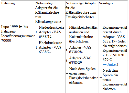
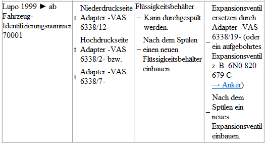
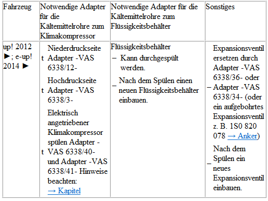
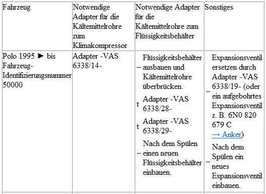
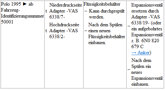
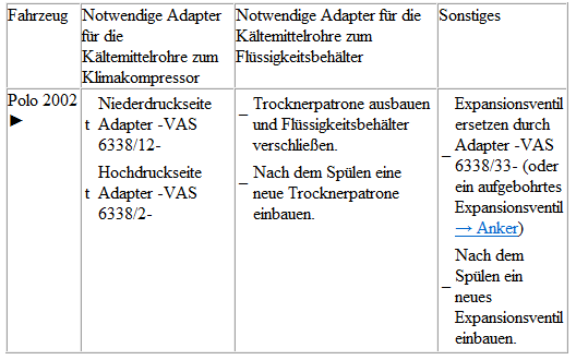
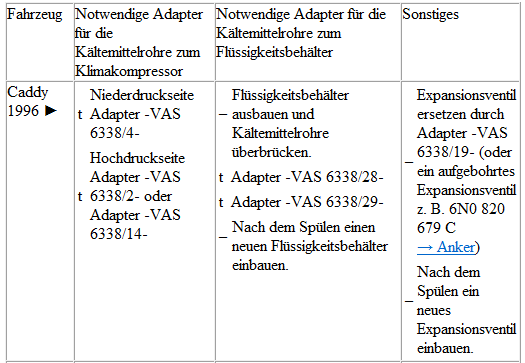
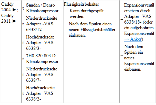
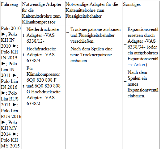
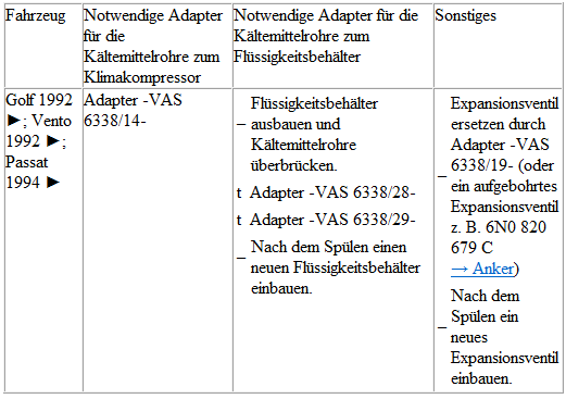
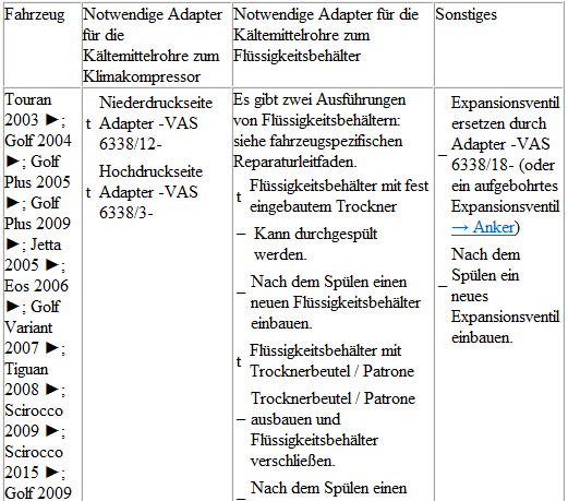
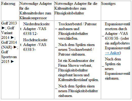
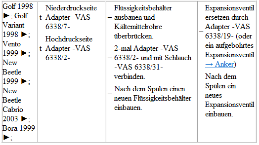
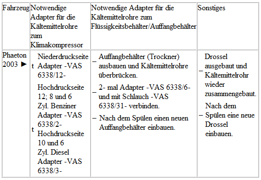
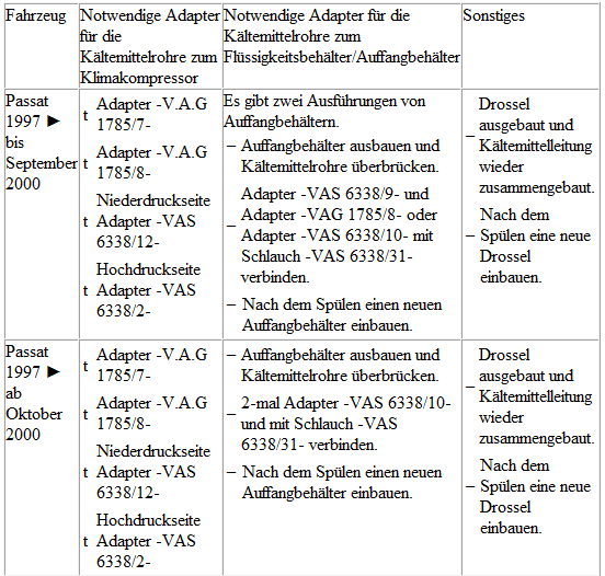
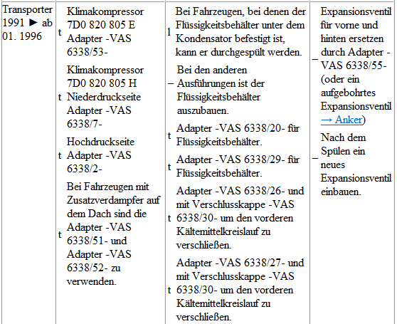
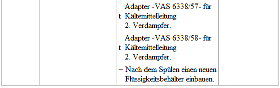
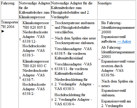
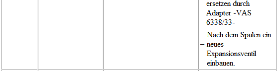
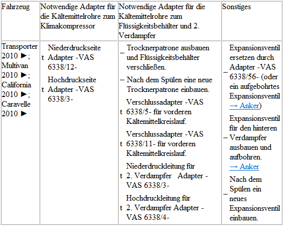
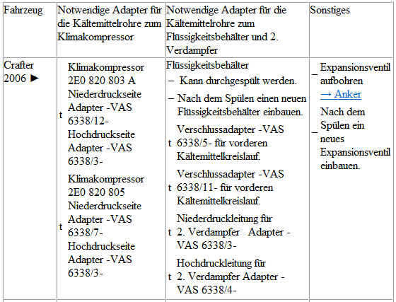
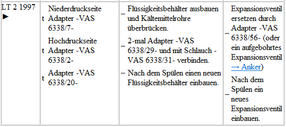
- The table below lists the various adapters required to connect the A/C service station to the refrigerant circuit for flushing and for bridging the removed liquid reservoir or accumulator and the expansion valve (vehicle-specific).
- Connect the two adapters installed for the removed accumulator or liquid reservoir with a charging hose with 5/8-18 UNF fittings (short version, e.g. charging hose -VAS 6338/31-) (included in adapter case PKW set VW/Audi -VAS 6338/1-).
- If a flushed refrigerant circuit is not reassembled immediately after flushing, leave the adapters on the connections and seal the connections on the adapters with sealing caps -VAS 6338/30- (from adapter case PKW set VW/Audi -VAS 6338/1-).
- Depending on the version of the A/C compressor and the production period, various connection and sealing techniques are used on the refrigerant circuit → Heating, Air Conditioning.
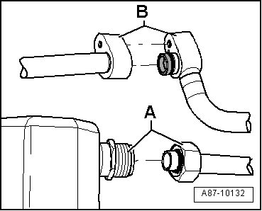
Block or screw connections
Screw connection -A-
Block connection -B-
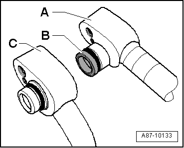
Block connections with different sealing types
Block connection with radial sealing connection -A- (with plastic or metal guide -B-)
- Block connection with axial sealing connection -C-
Fox 2005
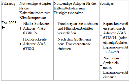
Lupo 1999
up! 2012; e-up! 2014
Polo 1995
Polo 2002
Caddy 1996; Caddy 2004; Caddy 2011
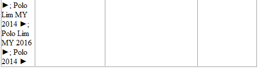
Polo 2010; Polo KH IN 2010; Polo KH IN 2015; Polo Lim IN 2011; Polo Lim In 2016; Polo Lim RUS 2011; Polo Lim RUS 2016; Polo KH MY 2014; Polo KH MY 2015; Polo Lim MY 2014; Polo Lim MY 2016; Polo 2014
Golf 1992; Vento 1992; Passat 1994
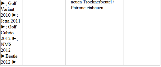
Touran 2003; Golf 2004; Golf Plus 2005; Golf Plus 2009; Jetta 2005; Eos 2006; Golf Variant 2007; Tiguan 2008; Scirocco 2009; Scirocco 2015; Golf 2009; Golf Variant 2010; Jetta 2011; Golf Cabrio 2012; NMS 2012; Beetle 2012; Golf 2013
Golf 2013; Golf Variant 2014; Golf 2014 (NAR); Golf Sportsvan 2015
Golf 1998; Golf Variant 1998; Vento 1999; New Beetle 1999; New Beetle Cabrio 2003; Bora 1999;
Phaeton 2003
Passat 1997
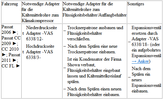
Passat 2006; Passat CC 2009; CC 2010; Passat 2011; CC FL
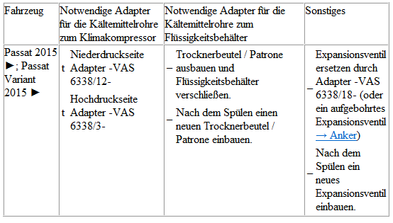
Passat 2015; Passat Variant 2015

Note
The Passat 2015 and Passat Variant 2015 with BiTurbo engine are not flushed. The effort to remove the expansion valve is too high. If the A/C compressor is damaged, check whether metal debris has entered the condenser and whether there is debris at the condenser outlet. If there is debris at the inlet but none at the outlet, only the condenser and A/C compressor need to be replaced.
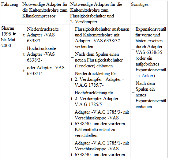
Sharan 1996

Note
On vehicles with a 2nd evaporator (Sharan), the front and rear refrigerant circuits must be flushed separately. The front refrigerant circuit must be sealed with adapter -V.A.G 1785/1-, adapter -1785/3- and sealing caps -VAS 6338/30-.
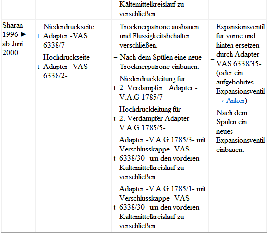
Sharan 2011; Sharan 2016

Note
On vehicles with a 2nd evaporator (Sharan), the front and rear refrigerant circuits must be flushed separately. The front refrigerant circuit must be sealed with adapter -V.A.G 1785/1-, adapter -1785/3- and sealing caps -VAS 6338/30-.
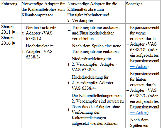
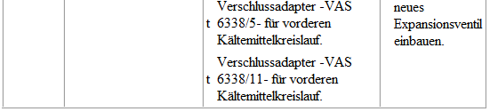
Touareg 2003; Touareg 2010; Touareg 2015; Touareg Hybrid 2010

Note
On vehicles with a 2nd evaporator (Touareg), the front and rear refrigerant circuits must be flushed separately. The front refrigerant circuit must be sealed with sealing adapter -VAS 6338/5- and sealing adapter -VAS 6338/11-.
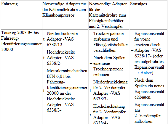
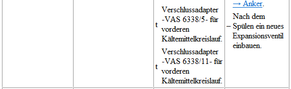
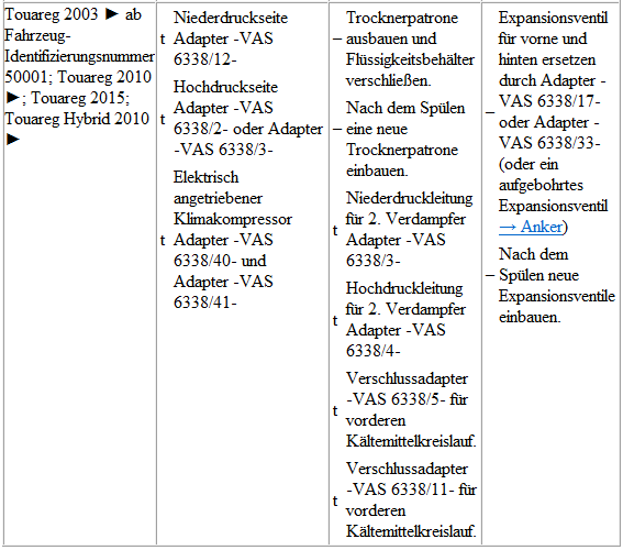
Transporter 1991

Note
On vehicles with a 2nd evaporator, the front and rear refrigerant circuits must be flushed separately. The front refrigerant circuit must be sealed with sealing adapter -VAS 6338/5- and sealing adapter -VAS 6338/11-.
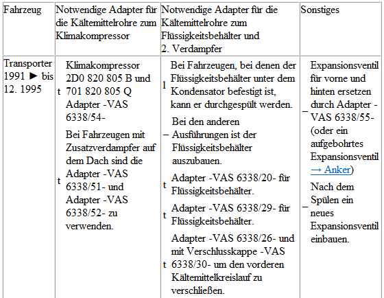
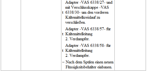
Transporter 2004

Note
On vehicles with a 2nd evaporator, the front and rear refrigerant circuits must be flushed separately. The front refrigerant circuit must be sealed with sealing adapter -VAS 6338/5- and sealing adapter -VAS 6338/11-.
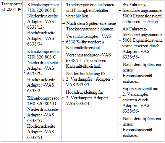
Transporter 2010; Multivan 2010; California 2010; Caravelle 2010;

Note
On vehicles with a 2nd evaporator, the front and rear refrigerant circuits must be flushed separately. The front refrigerant circuit must be sealed with sealing adapter -VAS 6338/5- and sealing adapter -VAS 6338/11-.
Crafter 2006; LT 2 from 1997

Note
On vehicles with a 2nd evaporator, the front and rear refrigerant circuits must be flushed separately. The front refrigerant circuit must be sealed with sealing adapter -VAS 6338/5- and sealing adapter -VAS 6338/11-.
Amarok 2011
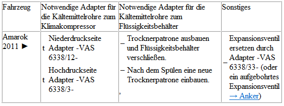
Golf 2009 blue e-Motion
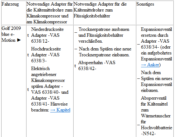
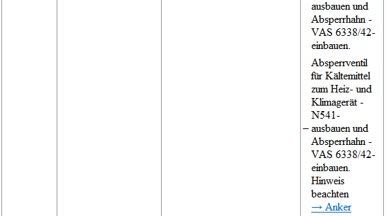
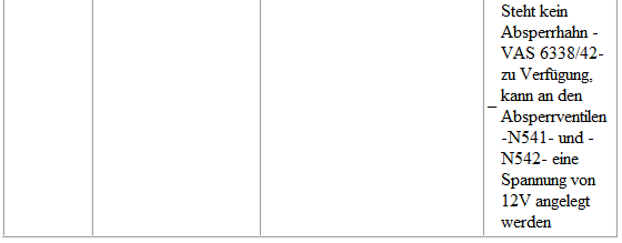
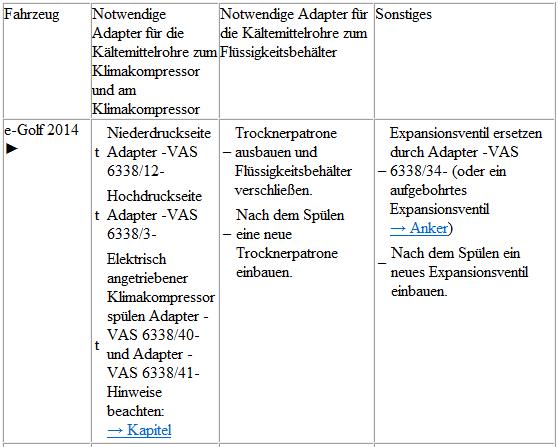
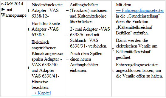
e-Golf 2014 and e-Golf 2014 with heat pump
Golf Hybrid 2014
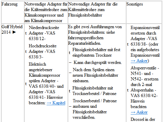
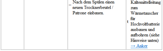

Note
On the Golf Hybrid 2014, the refrigerant circuit is flushed in 2 sections. In the first flushing cycle, the adapter for shut-off valve -N541- is open and the adapter for shut-off valve -N542- is closed. This flushes the refrigerant circuit with the evaporator in the heating and A/C unit. In the second flushing cycle, the adapter for the shut-off valve