Shift Actuation
Installation Position - Shift Actuation

Note
- For work on the shift actuation in the engine compartment, disconnect the ground cable from the battery → Electrical System.
- Remove and install shift actuation.
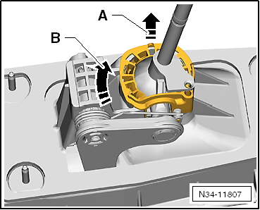
-Arrow A- shows the shift movement and the shift cable
-Arrow B- shows the select movement and the select cable
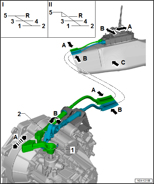
- Shift cable for shift movement
- Select cable for select movement
- Heat Shield
- Remove before removing shift actuation
- Gear shift lever
- Deflection lever
- up! - up to 02 14 - shift lever is NOT pressed down to engage reverse gear
- up! - from 03 14 and Polo - shift lever is pressed DOWN to engage reverse gear
Overview - Shift Actuation
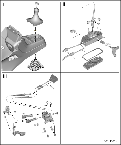
- "Assembly overview - shift knob and cover".
- "Assembly overview - shift lever and shift housing".
- "Assembly overview - actuating cables".
Assembly overview - shift knob and cover
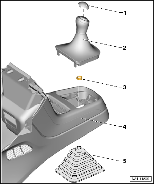
- Badge
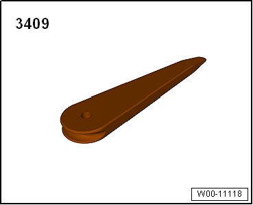
- can be carefully pried off the plastic or leather shift knob with release wedge -3409-
- Different versions for the following variants:
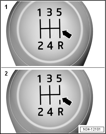
- Shift lever is NOT pressed down to engage reverse gear
- Shift lever is pressed DOWN to engage reverse gear
- Differentiation
- Assign badge via → Electronic Parts Catalog (ETKA).
- Shift knob
- with boot
- Shift knob and boot cannot be separated from each other
- always replace together
- Remove and install
- Different size of shift knob in the shift lever receptacle area for the following variants:
- Shift lever is NOT pressed down to engage reverse gear
- Shift lever is pressed DOWN to engage reverse gear
- assign via → Electronic Parts Catalog (ETKA).
- Clamp
- for fastening shift knob to shift lever
- replace after removal
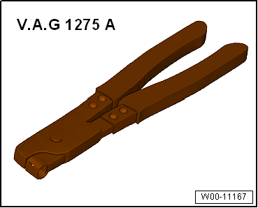
- fasten on shift knob with hose clamp pliers -V.A.G 1275 A-
- Upper part of center console
- up!: Combined into one part with the center console cover
- Center console cover separate on some equipment variants
- assign via → Electronic Parts Catalog (ETKA).
- Noise damper
- not on all vehicles
- Arrow on noise damper points in direction of travel
- Locking lugs are arranged at different intervals
- therefore can only be installed in one position
Assembly overview - shift lever and shift housing
Assembly overview - shift lever and shift housing, - shift lever is NOT pressed down to engage reverse gear

Note
- Grease bearing points and sliding surfaces.
- Assign grease via → Electronic Parts Catalog (ETKA).
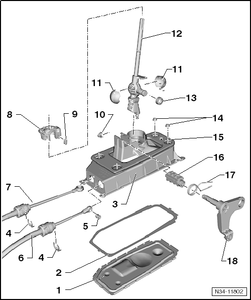
- Base plate
- For removal, bend tabs open
- install
- Gasket
- replace after removing floor plate
- shift housing
- retaining washer
- do not damage cables during removal
- replace after removal
- Bushing
- selector cable
- pry off selector bracket
- press onto selector bracket inside shift mechanism
- Installation position
- shift cable
- pry off shift lever guide
- press onto shift lever guide inside shift mechanism
- Installation position
- Bearing shell
- is damaged during removal
- replace after removal
- Damping
- remove and install
- Clip
- secures selector bracket
- check for damage
- Bearing shell
- Installation position
- place onto shift lever
- Shift lever and bearing shells are a replacement part
- shift lever
- Shift lever and bearing shells are a replacement part
- Bearing bush
- Installation position
- place onto shift lever
- supports shift lever in selector bracket
- Hex nut
- 4 pieces
- M 6: 8 N·m
- M 8: 25 N·m
- Gasket
- between shift housing and underbody
- replace after removing shift housing
- Self-adhesive
- glue to shift housing
- Bearing bush
- Installation position
- Compression spring
- selector bracket
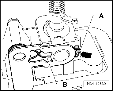
Remove and install damper -arrow-
- Push tab -A- of compression spring to the right until it is next to damper -arrow-.
- Move shift lever to the right; pull off damper.
- After installing damper, tabs -A- and -B- must rest against damper.
Installation overview - shift lever and shift housing, - shift lever is pressed "down" to engage reverse gear
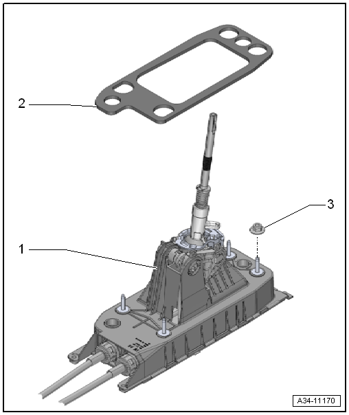
- shift mechanism
- Shift lever is pressed DOWN to engage reverse gear
- not serviceable
- Shift cable and selector cable cannot be removed
- Remove and install
- Gasket
- replace after removing shift mechanism
- Hex nut
- 4 pieces
- M 6: 8 N·m
- M 8: 25 N·m
Installation overview - gear cables

Note
- Grease bearing points and sliding surfaces.
- Assign grease via → Electronic Parts Catalog (ETKA).
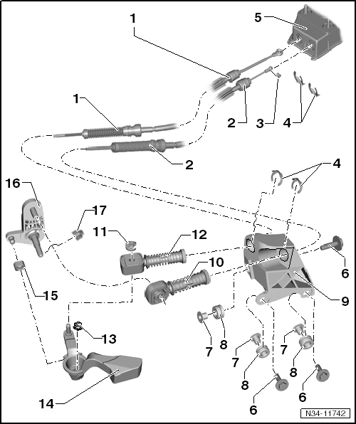
- shift cable
- connect to cable retainer
- Installation position
- Shift lever is NOT pressed "down" to engage reverse gear: - Shift cable and selector cable can be removed (up! only)
- Shift lever is pressed "down" to engage reverse gear: - Shift cable and selector cable cannot be removed (up! and Polo)
- selector cable
- connect to cable retainer
- Installation position
- Shift lever is NOT pressed "down" to engage reverse gear: - Shift cable and selector cable can be removed (up! only)
- Shift lever is pressed "down" to engage reverse gear: - Shift cable and selector cable cannot be removed (up! and Polo)
- Bushing
- retaining washer
- do not damage cables during removal
- replace after removal
- shift housing
- Shift lever is NOT pressed "down" to engage reverse gear: - Shift mechanism can be disassembled (up! only)
- Shift lever is pressed "down" to engage reverse gear: - Shift mechanism cannot be disassembled (up! and Polo)
- Hex bolt
- 3 pcs.
- for cable abutment bracket
- 25 N·m
- Spacer
- 3 pcs.
- for cable abutment bracket
- Grommet
- 3 pcs.
- Mounting of cable abutment bracket on transmission
- cable abutment bracket
- remove from transmission
- adjust shift mechanism after installation
- cable retainer
- remove and install
- adjust shift mechanism after installation
- for selector cable on deflection lever
- remove from deflection lever
- press onto deflection lever
- Assignment
- retaining washer
- replace after removal
- cable retainer
- remove and install
- adjust shift mechanism after installation
- for shift cable on transmission shift lever
- Assignment
- Hex nut
- Gear shift lever
- grease before installing
- can be replaced with shift mechanism installed
- Installation position
- install
- adjust shift mechanism after installation
- sliding shoe
- Sliding shoe and deflection lever are a replacement part
- Deflection lever
- grease before installing
- Installation position
- adjust shift mechanism after installation
- remove and install together with cable retainer
- Clip
- secures deflection lever
- check for damage
remove and install shift knob
Required Special Tools, Test and Measuring Equipment and Auxiliary Items
- Hose clamp pliers -V.A.G 1275 A-
- up!, removal wedge -3409-
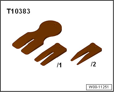
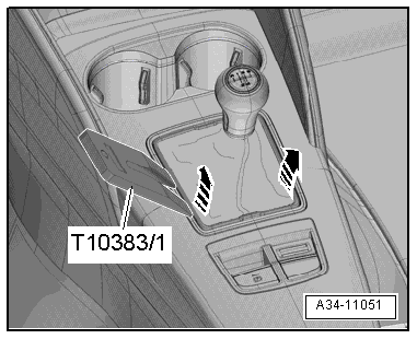
- Polo, wedges -T10383-
Removing
up!
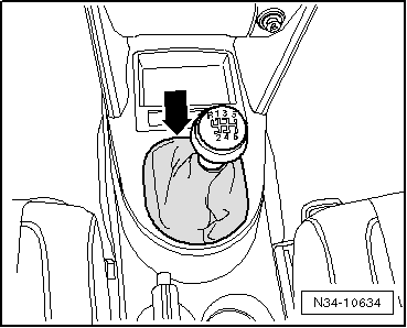
- Carefully pry shift lever boot off center console insert with removal wedge -3409- -arrows-.
Polo
- Carefully pry shift lever boot off center console insert with wedge -T10383- -arrows-.
- Or carefully pry out shift lever boot with removal wedge -3409-.
Continuation for all
- Slide shift lever boot up over shift knob.
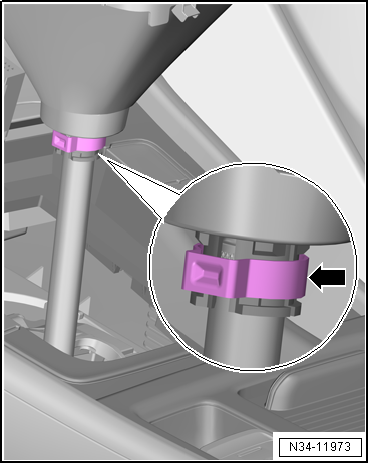
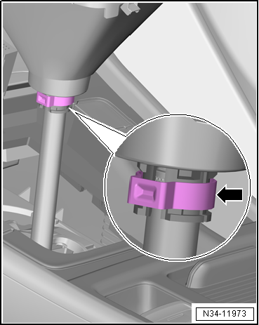
- Open clamp -arrow- and pull off shift knob together with shift lever boot.
Installing
Installation is carried out in the reverse order, observing the following:
- Press shift knob together with shift lever boot onto shift lever until it stops.
- Secure shift knob to shift lever with clamp -arrow-. Use hose clamp pliers -V.A.G 1275 A- for this.
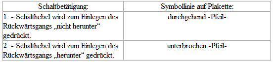
Identification of plaques
remove and install shift mechanism
Required Special Tools, Test and Measuring Equipment and Auxiliary Items
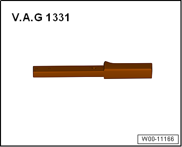
- Torque Wrench -V.A.G 1331-
Removing
- Disconnect the negative battery cable → Electrical System.
- Remove boot with shift knob and, if equipped, noise damper from center console frame.
up!
- Remove center console insert → Body assembly work, interior.
- Unscrew center console upper section at rear area → Body assembly work, interior.
- Unscrew center console lower section in footwell → Body assembly work, interior.
Polo
- Remove center console with center console mounting bracket → Body assembly work, interior.
Continuation for all
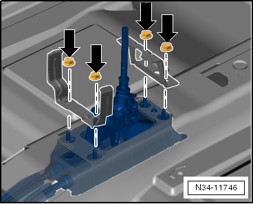
- Unscrew nuts -arrows- for shift housing and, if equipped, for center console mounting bracket; carefully lift center console lower section slightly for this.
- Lower shift housing.
- If equipped, remove damper from shift housing → Body assembly work, interior.
- Remove the complete air filter housing if it is located above the shift linkage.
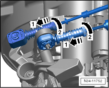
- Pull the cable retainer of the shift cable and selector cable forward to the stop in direction of arrow 1, then lock it in direction of arrow 2.
up!
On some equipment variants, the shift cable is only accessible from below the vehicle in the direction of the arrow.
Continuation for all
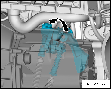
- Remove the retaining washers (arrows) for the cables from the cable bracket.
- Disconnect the exhaust system at the front separation point.
- Unhook the exhaust system.
- Remove the heat shield → Body Assembly Work, Exterior.
- Swivel the shift housing down and remove it together with the cables.
Installing
Installation is in reverse order, observing the following:
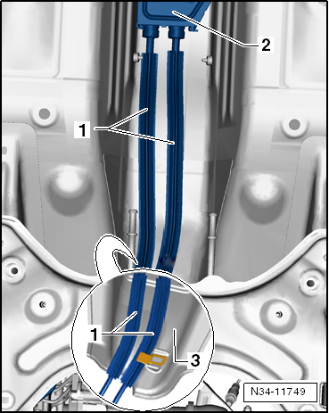
- Route the cables -1- from the shift linkage -2- to the transmission as follows:
- The cables must run parallel to each other up to the cable bracket on the transmission.
- The cables must be routed in the channel provided in the heat shield -3-.
up!
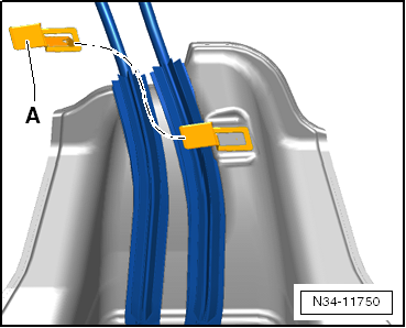
The cables and heat shield are held in position relative to each other by clip -A-, if fitted.
Continuation for all
- Insert the cables into the cable retainers.
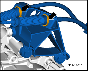
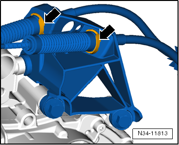
Press the retaining washers (arrows) for the cables into the cable bracket.
- Align the shift housing parallel to the body.
- The distance to the body must then be the same on both sides.
- Assemble the center console and tighten the screws → Body Assembly Work, Interior.
- Install the center console insert → Body Assembly Work, Interior.
- Replace clamp -arrow-.
- Install the heat shield → Body Assembly Work, Exterior.
- Assemble the exhaust system and hook it in.
- Adjust gear shift linkage.
- If removed, install the complete air filter housing.
- Connect the battery and observe the work steps after connecting the battery → Electrical System.
Tightening torques
Shift housing to body.
Cable bracket to transmission
Repairing shift linkage
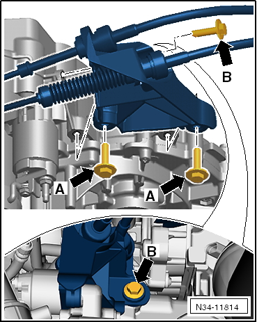
Removing cable bracket from transmission
The screws -arrow A- are accessible from the engine compartment.
The screw -arrow B- is accessible from below the vehicle.
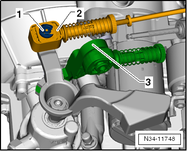
Removing and installing cable retainer for shift cable and deflection lever
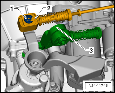
- Remove the retaining washer -1- for the shift cable -2- from the transmission shift lever, and pull the shift cable retainer off the pin.
- Remove the cable retainer for the deflection lever -3- together with the deflection lever.
Assigning the cable retainers
The bores in the cable retainers have different diameters.
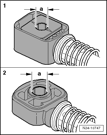
Cable retainer for: dimension "a"
1. Shift cable to transmission shift lever - 8.5 mm
2. Selector cable to deflection lever - 10 mm
The bores in the cable retainers have different diameters.
- Apply a small amount of grease to the pin of the transmission shift lever.
Assign grease via → Electronic Parts Catalog (ETKA).
- Replace the retaining washer -1- for the shift cable -2- after removal.
- Install the deflection lever -3- and the cable retainer together.
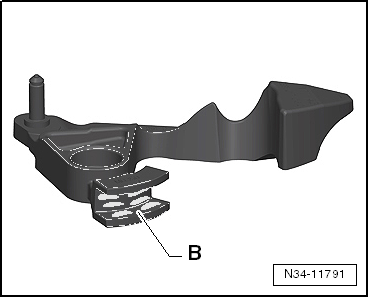
Greasing the transmission shift lever
- Grease the guide rail -B- of the transmission shift lever, which the deflection lever engages, with particular care.
- Assign grease via → Electronic Parts Catalog (ETKA).
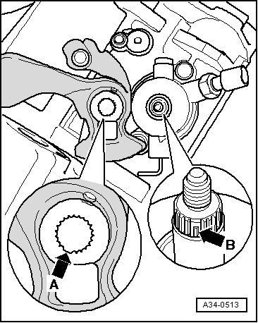
Installing the transmission shift lever
- When fitting the transmission shift lever, make sure the tooth gap -arrow A- is placed over the interrupted tooth pitch of the shift shaft -arrow B-.

Note
The illustration of the transmission shift lever may differ from the original part.
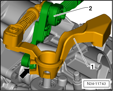
Installed position of transmission shift lever/deflection lever
- Gear shift lever
- The deflection lever engages the guide rail of the transmission shift lever via the sliding shoe -arrow-.
Greasing the deflection lever
- Grease shaft -A- of the deflection lever with particular care over the entire area -arrows-, grease quantity 0.2 grams.
- Assign grease via → Electronic Parts Catalog (ETKA).

Note
The illustration of the deflection lever may differ from the original part.
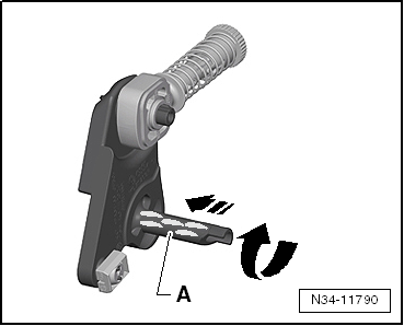
Removing and installing deflection lever with cable retainer
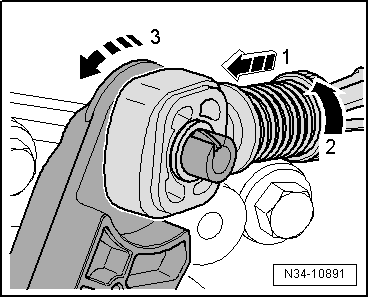
- To remove the deflection lever, the cable retainer must be disconnected from the selector cable.
This prevents damage to the selector cable.
- The cable retainer may only be removed when the deflection lever has been removed.
- Pull the locking mechanism forward to the stop in direction of arrow 1, then lock it to the left in direction of arrow 2.
- Then press the deflection lever forward (direction of arrow 3).
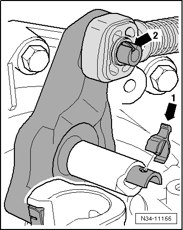
- Pull off clip -arrow 1- and remove the deflection lever together with the cable retainer.
The cable retainer must be positioned behind the detent -arrow 2-.

Note
- Grease bearing points and sliding surfaces.
- Assign grease via → Electronic Parts Catalog (ETKA).
- Press the cable retainer onto the deflection lever.
- Insert the deflection lever together with the cable retainer up to the stop.
- Clip -arrow 1- secures the deflection lever.
- Make sure the clip is securely engaged.
- The cable retainer must be positioned behind the detent -arrow 2-.
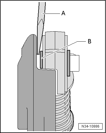
Levering the cable retainer for selector cable off the deflection lever
- The deflection lever has been removed.
- Insert a flat-blade screwdriver -A- between the bushing -B- and the deflection lever.
Pressing the cable retainer onto the deflection lever
- The deflection lever has been removed.
- The cable retainer may only be pressed on at the bushing -arrow-.
- The cable retainer must move freely on the deflection lever.
- It must be positioned behind the detent -arrow 2-.
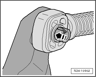
Adjusting shift linkage
Required Special Tools, Test and Measuring Equipment and Auxiliary Items
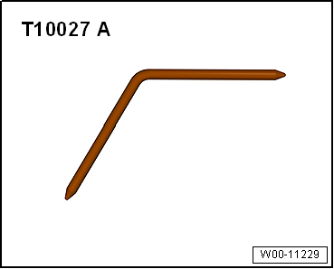
- Locating pin -T10027 A-

Note
- The following conditions are required for correct shift adjustment:
- Operating and transmission elements of the shift linkage must be in perfect condition.
- The shift linkage moves smoothly.
- Furthermore, the transmission, clutch and clutch actuation must be in perfect condition.
- Transmission in neutral position.
- The cable retainers of the shift cable and selector cable must be accessible.
- Remove the air filter housing if this prevents access to the transmission shift lever and the cable retainers of the shift cable and selector cable.
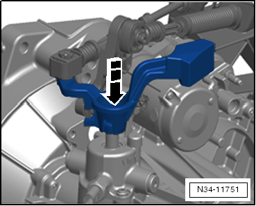
- Check the neutral position by pressing the transmission shift lever down in direction of the arrow.
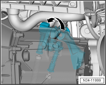
- The transmission shift lever returns to its initial position automatically.
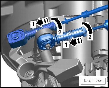
- Pull the cable retainer of the shift cable and selector cable forward to the stop in direction of arrow 1, then lock it in direction of arrow 2.
up!
On some equipment variants, the shift cable is only accessible from below the vehicle in the direction of the arrow.
Continuation for all
- Remove the shift lever boot and, if fitted, the noise insulation from the centre console.
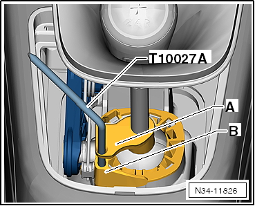
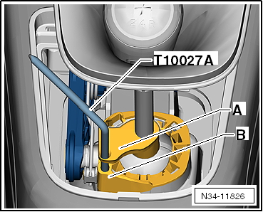
Now lock the shift lever as follows:
- Place the shift lever in the neutral position.
- Insert the locking pin -T10027 A- through hole -A- into hole -B-.
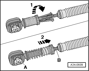
- The selector cable and shift cable -B- are in the retainers -A- without tension.
- Now turn the locking mechanism on the cable retainer of the shift cable and selector cable in -direction of arrow 1- until it stops.
The spring presses the locking mechanism back into its initial position -direction of arrow 2-.
- Pull the locking pin out of holes -A- and -B-.
- Install the noise insulation, if fitted.
- Press the boot into the console.
- Check the shift shaft for free movement.
- If removed, install the complete air filter housing.
Check gear shift operation
- The shift lever must be in the neutral position in the 3rd/4th gear gate.
- Depress the clutch.
- Shift through all gears several times.
- If the shift lever must be pressed "down" to engage reverse gear, pay particular attention to the function of the reverse gear lock.
- If a catch still occurs when engaging a gear repeatedly, adjust the gear shift linkage again.
Disassemble and assemble gear shift linkage
Disassemble and assemble gear shift linkage, - shift lever is not pressed "down" to engage reverse gear
Required Special Tools, Test and Measuring Equipment and Auxiliary Items
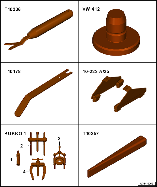
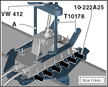
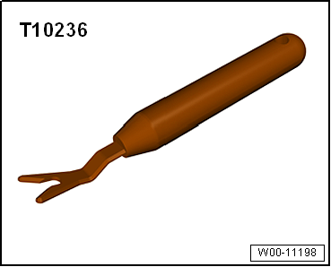
- Release tool -T10236-
- Pressure ram -VW 412-
- Assembly tool -T10178-
- Adapter -10 - 222 A /25-
- 2 = Counter support, e.g. from -Kukko- series 16
- Wedge -T10357-
Disassembling
- Remove the gear shift linkage.
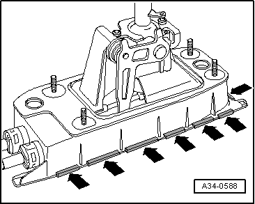
- Bend open the tabs -arrows- of the floor plate with a screwdriver (only the tabs in the left area of the floor plate are marked here).
- Remove the floor plate.
- Remove the seal from the shift housing.
- Remove the shift cable and selector cable from the shift housing.
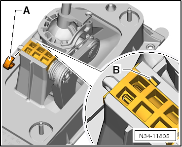
- Pull clip -A- out of the selector bracket bearing shaft.
- Use a screwdriver to press down catch -B- of the selector bracket bearing bushing. Break off the catch if necessary.
- Press the selector bracket bearing bushing out of the shift housing.
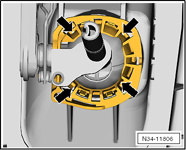
- Use a screwdriver to press the catches -arrows- of the bearing shell towards the bearing ball of the shift lever guide. Break off the catches if necessary.
- Lever the bearing shell with the shift lever out of the shift housing -arrow A-.
- Then press the bearing shell off the bearing ball of the shift lever guide -arrow B- and remove the shift lever with the selector bracket.
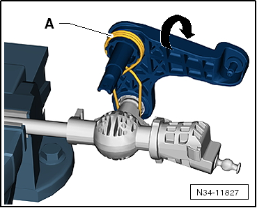
- Clamp the shift lever with the selector bracket in a vice with protective jaws.
- Press the selector bracket off the shift lever in -direction of arrow-.

Caution!
The compression spring -A- can spring off the selector bracket uncontrolled.
Assembly
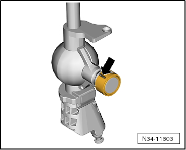
- Place the bearing bushing onto the shift lever.
Installation position of bearing bushing
The circumferential slots -arrow- face the shift lever.
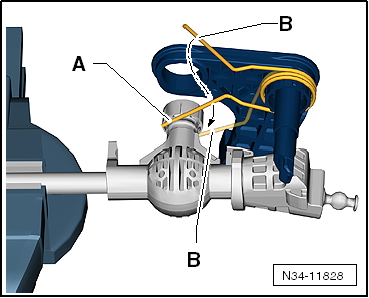
- Install the selector bracket together with the compression spring onto the shift lever:
- Legs -A- and -B- must point in the same direction
- Insert leg -A- of the compression spring from above into the guide (towards the shift lever).
- Carefully pull leg -B- of the compression spring downward and insert it into the guide (towards the shift lever).
- Press the selector bracket -arrow- onto the shift lever.

Caution!
The compression spring must not spring off the selector bracket uncontrolled.
- If removed, press the bearing shells onto the shift lever.
Installation position of bearing shells
The lugs -A- must be located in the holes -B-.
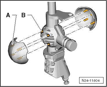
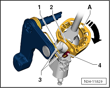
- Place a new bearing shell -A- onto the shift lever.
- Grease bearing shell -A- and the bearing shells of the shift lever.
- Turn the bearing shell in -direction of arrow-.
- The pin -1- must be located in the recess -2- of bearing shell -A-.
- The spring -3- rests against the damper -4- on both sides.
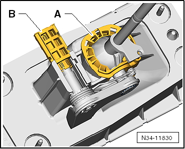
- Press bearing shell -A- together with the shift lever and selector bracket into the shift housing. Observe installation position.
- All 4 locking lugs must engage.
- Insert the bearing bushing -B- for the selector bracket.
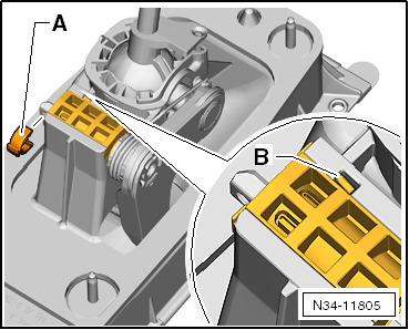
Installation position of bearing bushing
The catch -B- must lock into the recess of the shift housing.
- Secure the selector bracket with clip -A-.
- Install the shift cable and selector cable and.
Secure floor plate to shift housing
- Place a new seal onto the floor plate.

Caution!
Risk of damage to shift housing and floor plate.
Only slightly tighten the shift housing.
- Secure the floor plate by crimping the tabs -arrows- all the way around (only the tabs in the left area of the floor plate are marked here).
- The tabs can be crimped using wedge -T10357-.
- A- = Counter support, e.g. from -Kukko- series 16
- Glue a new seal onto the shift housing.
- Install the gear shift linkage.
- Adjust gear shift linkage.
Remove and install operating cable
Remove and install operating cable, - shift lever is not pressed "down" to engage reverse gear
Required Special Tools, Test and Measuring Equipment and Auxiliary Items
- Release tool -T10236-
Removing
- Remove the gear shift linkage.
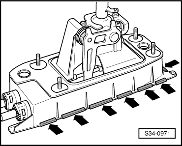
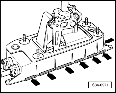
- Bend open the tabs -arrows- of the floor plate with a screwdriver (only the tabs in the left area of the floor plate are marked here).
- Remove the floor plate.
- Remove the gasket.
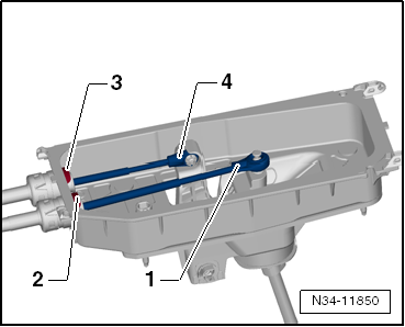
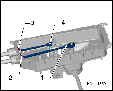
- Press shift cable -1- and selector cable -4- off the shift lever and selector lever, e.g. with release tool -T10236- or a screwdriver.
- Pull off retaining washers -2- and -3-.
- Pull the shift cable and selector cable off the shift housing.
Installing
Installation is carried out in the reverse order, observing the following:
- Secure the shift cable and selector cable to the shift housing with retaining washers -2- and -3-.
- Press shift cable -1- onto the shift lever and selector cable -4- onto the selector lever in the shift housing.
- Secure the floor plate by pressing the tabs -arrows- onto the shift housing.
- Install the gear shift linkage.
- Adjust gear shift linkage.
Replace sealing ring for shift shaft
Required Special Tools, Test and Measuring Equipment and Auxiliary Items
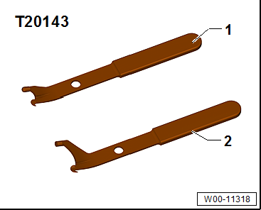
- Pry lever -T20143/1-
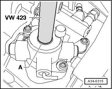
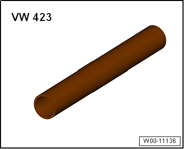
- Tube piece -VW 423-
- Sealing grease → Electronic Parts Catalog (ETKA)
- If the air filter housing is located above the shift mechanism, remove the complete air filter housing.
- Remove battery and battery carrier → Electrical system.
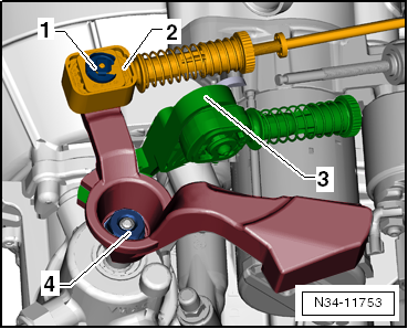
- Remove locking washer -1- for the shift cable -2- from the transmission shift lever.
- Pull the shift cable off the pin.
- Remove deflection lever -3- together with the cable retainer.
- Remove transmission shift lever by unscrewing nut -4-.
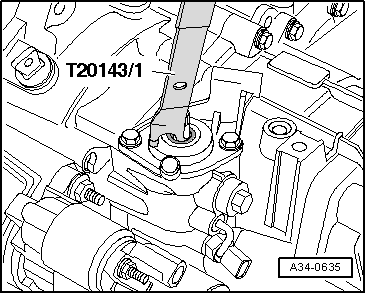
- Pry out the sealing ring using pry lever -T20143/1-.
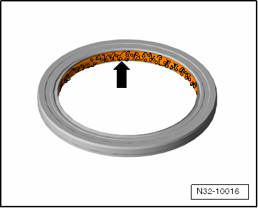
- Fill the space between sealing lip and dust lip -arrow- halfway with sealing grease -G 052 128 A1-.
- Press in sealing ring with tube piece -VW 423- until it stops.
Installation is performed in reverse order. Observe the following:
- Install the transmission shift lever on the transmission shift shaft.
- Adjust gear shift linkage.
- Tighten the hex nut to the specified tightening torque.
- Install battery → Electrical System.
- If removed, install the complete air filter housing.