Fuel level sender

Fuel tank protective flange located under the luggage compartment floor
1 – supply line to the injection system;
2 – return fuel line from the injection system (arrows indicate the retaining clips for removing this fuel line);
3 – connector of the fuel pump and fuel sender.

Shown on a 5-cylinder engine:
1 – line to the activated charcoal canister;
2 – solenoid valve;
3 – fuel line to the throttle body.
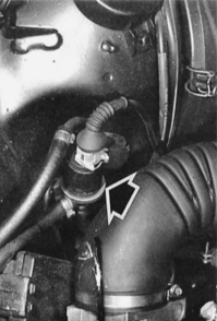
The arrow points to the activated charcoal canister solenoid valve on the 6-cylinder engine model.

The activated charcoal canister is located at the rear of the right front wheel well (shown with the splash guard removed).
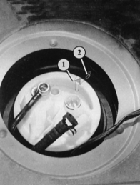
Installation position of the protective flange: the arrow on the flange (1) must align with the mark on the fuel tank (2).
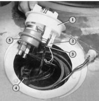
Illustration shows the protective flange (1) removed: 2 – fuel pump electrical wire;
3 – fuel gauge sender wire;
4 – return line to the fuel tank;
5 – fuel accumulator (only on 5-cylinder engine models with KE-III-Jetronic injection).
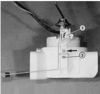
The strainer shown here is normally glued inside the fuel tank; it is shown separately for better clarity. The fuel sender (1) can be removed after pressing the button (arrow). This releases the lock. The sender can now be pulled out.
The fuel sender is mounted on top of the fuel pickup housing, located inside the middle of the fuel tank. For a description of its operation, refer to the chapter Instruments and Auxiliary Devices.
Note that, depending on the different fuel tank shapes, different fuel senders are used for front-wheel drive and all-wheel drive models. Identification: a sender with a rectangular float is for front-wheel drive models, a sender with a spherical float is for all-wheel drive models.
Note: the fuel gauge is not a high-precision instrument. An incorrectly indicating sender can be compensated by adjusting the gauge on the instrument panel (refer to the chapter Instruments and Auxiliary Devices).
Test yourself
A quick Audi 80 quiz: every answer comes with an explanation and a link to the manual page.