Cylinder Head Cover. Removal and Installation
Special Service Tools / General Equipment
 |
303-1097 Locking Tool, Variable Camshaft Timing Oil Control Valve TKIT-2010B-FLM TKIT-2010B-RYAD |
 |
303-1556 Timing Belt Locking Tool TKIT-2010B-FLM TKIT-2010B-RYAD |
 |
303-748 Crankshaft Locking Tool TKIT-2010B-FLM TKIT-2010B-RHD |
| Strap wrench | |
| Oil Drain Equipment | |
| Heat gun | |
| Hose Clamp Removal/Installation Tool | |
Materials
| Name | Specification |
|---|---|
| Flange Sealant CU7Z-19B508-A |
WSS-M2G348-A11 |
| Motorcraft® Metal Surface Preparation Wipes ZC-31-B |
- |
| Engine Oil — SAE 5W-20 — Semi-Synthetic Engine Oil XO-5W20-Q1SP |
WSS-M2C945-B1 |
| Motorcraft® Orange Concentrated Antifreeze/Coolant WSS-M97B44-D |
WSS-M97B44-D |
Removal
- Position the vehicle in NEUTRAL on the lift.
Refer to: Jacking and Lifting - Overview (100-02 Jacking and Lifting, Description and Operation). - Release the fuel system pressure.
Refer to: Fuel System Pressure Release (310-00A Fuel System — General Information — 1.5 L EcoBoost (118 kW/160 L PS) — I4, General Procedures). - Disconnect the battery ground cable.
Refer to: Battery Disconnect and Connect (414-01 Battery, Mounting and Cables, General Procedures). - Remove the following components:
- Remove the CAC inlet tube.
Refer to: Charge Air Cooler (CAC) Inlet Tube (303-12A Air Distribution and Filtration — 1.5 L EcoBoost (118 kW/160 L hp) — I4, Removal and Installation). - Remove the EVAP canister purge valve.
Refer to: Evaporative Emission Canister Purge Valve (303-13A Evaporative Emissions — 1.5 L EcoBoost (118 kW/160 L hp) — I4, Removal and Installation).
- Remove the CAC inlet tube.
- Drain the cooling system.
Refer to: Engine Cooling System Draining, Vacuum Filling and Air Bleeding (303-03A Engine Cooling — 1.5 L EcoBoost (118 kW/160 L hp) — I4, General Procedures). - Remove and discard the axle bearing lock nuts and the drive belt.

- Remove the bolts and set the axle bearing bracket aside.

- Remove the engine plug bolt.

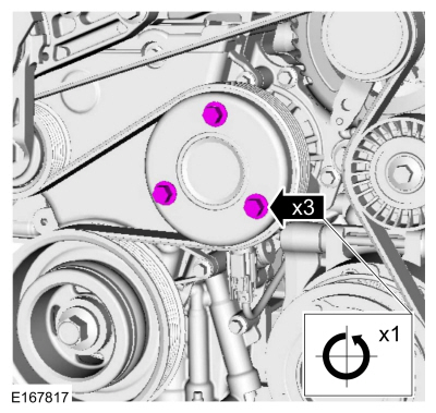
- Loosen the coolant pump pulley bolts.
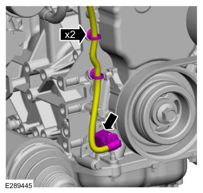
- Disconnect the crankshaft position sensor electrical connector and the wiring harness clips.
- If equipped, remove the clips and heat shield.
- Disconnect the turbocharger hose and clips.
Use the common service equipment: hose clamp removal/installation tool.
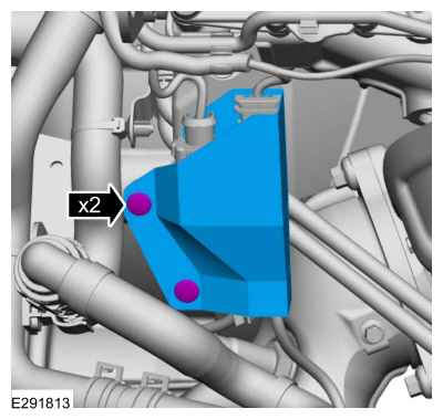
- Disconnect the electrical connectors from the bracket.

- Disconnect the turbocharger hose and clips.
- Disconnect the CHT sensor electrical connector.

- Remove the following components:
- Remove the high-pressure fuel pump drive block.
Refer to: High-Pressure Fuel Pump Drive Block (303-04A Fuel Charging and Controls – 1.5 L EcoBoost (118 kW/160 L PS) – I4, Removal and Installation). - Remove the brake vacuum pump.
Refer to: Brake Vacuum Pump — 1.5 L EcoBoost (118 kW/160 L hp) — I4 (206-07 Power Brake Actuation, Removal and Installation).
- Remove the high-pressure fuel pump drive block.
- Disconnect the PCM electrical connector.

- Disconnect the wiring harness bracket, disconnect the electrical connector, and set the wiring harness aside.

- Remove the wiring harness bolt. Disconnect the wiring harness clip and set the wiring harness aside.

- Disconnect the IAT sensor electrical connector and the wiring harness clip.

- Disconnect and set aside the coolant tube.
- Disconnect the KS electrical connector.
- Disconnect the KS electrical connector.

- Disconnect the TB (throttle body) electrical connector and the wiring harness clip.

- Disconnect the quick-connect couplings and move the coolant hoses aside.

- Disconnect the wiring harness clips.

- Disconnect the clip from the coolant tube bracket.

- Remove the turbocharger coolant tube clips.

- Remove the bolt and set aside the turbocharger cooling tube.

- Remove and discard the turbocharger coolant tube O-rings.

- Remove the bolts and the turbocharger heat shield.

- Remove the TC oil supply tube bolt and disconnect the tube from the engine.

- Remove and discard the TC oil supply tube assembly.

- Remove and discard the TC nuts.

- Remove and discard the TC mounting studs and gasket.

- Disconnect the coolant hose and set aside.
Use the common service equipment: hose clamp removal/installation tool.
- Remove the nut.
- Remove the stud and position the coolant outlet.

- Inspect the coolant outlet O-ring and replace it if damaged.

- Remove the TB (throttle body).
Refer to: Throttle Body (303-04A Fuel Delivery and Controls — 1.5 L EcoBoost (118 kW/160 L hp) — I4, Removal and Installation). - Remove the bolts and the intake manifold bracket.

- Disconnect and remove the engine breather hose.
Use the common service equipment: hose clamp removal/installation tool.
- Loosen the oil separator tube attaching bolt.

- Loosen the intake manifold attaching bolt.
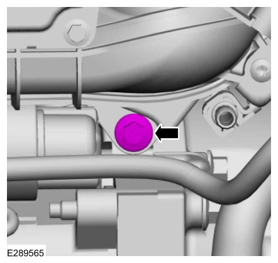
- Using a cable tie or rubber strap, secure the intake manifold bolt in the removed position.
- Remove the following components:
- Remove the engine mount.
Refer to: Engine Mount (303-01A — 1.5 L EcoBoost (118 kW/160 L hp) — I4, Removal and Installation). - Remove the auxiliary drive belt.
Refer to: Auxiliary Drive Belt (303-05A Auxiliary Drive — 1.5 L EcoBoost (118 kW/160 L PS) — I4, Removal and Installation).
- Remove the engine mount.
- Remove the coolant pump bolts and pulley.

- Remove the upper generator mounting stud and, if equipped, the bracket.
- Remove the alternator nut.

- Remove the alternator stud.

- Loosen the bolt and remove the generator.

- Remove the engine mount stud.

- Remove the nut, bolt and bracket.

- Remove the timing belt cover stud.
- Disengage the cover from the retainer and open it.
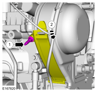
- Remove the engine front cover bolts.

- Remove the engine front cover.
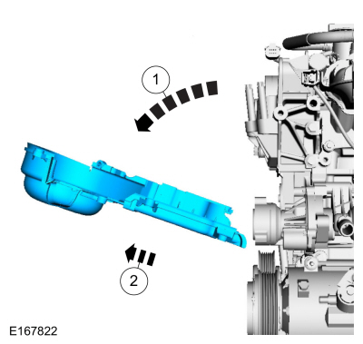
- Install a new timing belt if the old belt is contaminated with coolant or oil. Refer to Timing Belt (303-01A Engine — 1.5 L EcoBoost (118 kW/160 L PS) — I4, Removal and Installation).
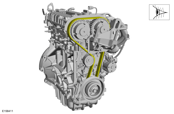
- Remove the bolts and the engine mount bracket.

- Slowly rotate the crankshaft to the 11 o'clock position.

Install the special service tool: 303-748 Crankshaft Locking Tool.
- Slowly rotate the crankshaft clockwise until the crankshaft counterweight aligns with the crankshaft TDC timing pin. The engine is now at TDC.

- Install the special service tool: 303-1556 Locking Tool, Timing Belt.
- Mark the component positions before removal.

NOTICE: Do not rotate the crankshaft or camshafts with the timing belt removed.
- Rotate the timing belt tensioner.
- Common equipment: locking pin
Install the locking pin.
- Carefully remove the timing belt from the VCT units.

- Remove the camshaft seals.
Refer to: Camshaft Seal (303-01A Engine — 1.5 L EcoBoost (118 kW/160 L PS) — I4, Removal and Installation). NOTICE: Use a heat gun to soften the flange sealant; this will assist in removing the camshaft cap. Failure to follow these instructions may damage the camshaft cap.
NOTICE: Do not pry on the camshafts during removal as this may damage the camshafts.
- Remove the 20 bolts.
- Remove the camshaft covers.
- Heat and remove the camshaft cap.
Use common service equipment: heat gun.
- Remove the camshafts.

- Remove the crankcase ventilation drain tube.

- Inspect the crankcase ventilation drain tube and replace it if damaged.

- Remove and discard the O-ring.

- Make sure the mating surfaces are clean and free of foreign material.

- Make sure the mating surfaces are clean and free of foreign material.

- Remove and discard the cylinder head bolts.

- Position the camshafts in the neutral position in the cylinder head. Install the 4 camshaft caps and 8 original bolts. Tighten the camshaft bearing cap bolts one turn at a time until they seat against the cylinder head.

- Remove the cylinder head.

- Remove and discard the cylinder head gasket.

- Inspect the cylinder head and cylinder block for distortion.
Refer to: Cylinder Head Distortion (303-00 Engine System — General Information, General Procedures).
Refer to: Cylinder Block Distortion (303-00 Engine System — General Information, General Procedures).
Installation
- Refer to the cylinder head.
Refer to: Cylinder Head (303-01A Engine — 1.5 L EcoBoost (118 kW/160 L PS) — I4, Disassembly and Assembly of Components). - Clean and inspect the turbocharger mounting flange.

NOTICE: Do not use metal scrapers, wire brushes, power abrasive discs or other abrasive means to clean the sealing surfaces. These tools leave scratches and gouges that create leak paths. Use a plastic scraper to remove all traces of the cylinder head gasket.
Make sure the mating surfaces are clean and free of foreign material.
Material: Motorcraft® Metal Surface Preparation Wipes / ZC-31-B
- Install the cylinder head gasket.

- Install the cylinder head.

NOTICE: Failure to follow the camshaft loosening procedure may damage the camshafts. Discard the camshaft bearing cap bolts.
If necessary, loosen the camshaft bearing cap bolts 1 turn at a time until all tension is released from the camshaft bearing caps. Remove the bolts, camshaft caps and camshafts. Discard the camshaft bearing cap bolts.
- Install the new cylinder head bolts and tighten them in the sequence shown.
Torque:
Stage 1: 44 lb-in (5 N·m)
Stage 2: 133 lb-in (15 N·m)
Stage 3: 26 lb-ft (35 N·m)
Stage 4: 90°
Stage 5: 90°
- Install the new mega cover O-ring seal.

- Install the crankcase ventilation drain tube.

- Apply a 2 mm diameter bead of flange sealant.
Material: Flange Sealant / CU7Z-19B508-A (WSS-M2G348-A11)
NOTICE: Failure to follow the camshaft tightening procedure may damage the camshafts.
NOTICE: Make sure the camshafts and camshaft bearing caps are installed in their original positions or engine damage may occur.
- Evenly tighten the bolts, one-half turn at a time, until the camshaft bearing caps and VCT bridge seat against the cylinder head.
Material: Engine Oil — SAE 5W-20 — Synthetic Engine Oil / XO-5W20-Q1SP (WSS-M2C945-B1)
Torque:
Stage 1: Tighten bolts 1 through 16 to: 62 lb-in (7 N·m)
Stage 2: Tighten bolts 17 through 20 to: 89 lb-in (10 N·m)
Stage 3: Tighten bolts 1 through 16 an additional: 45°
Stage 4: Tighten bolts 17 and 18 an additional: 70°
Stage 5: Tighten bolts 19 and 20 an additional: 53°

- Evenly tighten the bolts, one-half turn at a time, until the camshaft bearing caps and VCT bridge seat against the cylinder head.
- Install the camshaft seals.
Refer to: Camshaft Seal (303-01A Engine – 1.5 L EcoBoost (118 kW/160 L PS) – I4, Removal and Installation). - Install the timing belt on the VCT units.

- Make sure the timing belt is correctly aligned.
- Remove the retaining pin.

- Before removal, make sure that the components are installed in the specified position.
- Remove the special service tool: 303-1556 Timing Belt Locking Tool.

Remove the special service tool: 303-748 Locking Tool, Crankshaft.
Remove the special service tool: 303-1097 Locking Tool, Variable Cam Timing Oil Control Valve.
- Install the engine mount bracket and bolts.
Torque: 41 lb-ft (55 N·m)
- Install the engine front cover.

- Install the front engine cover bolts.
Torque: 89 lb-in (10 N·m)
- Install the front engine cover side panel and stud.
Torque: 89 lb-in (10 N·m)
- Install the bracket, nut and bolt.
Torque:
Bolt: 17 lb-ft (23 N·m)
Nut: 62 lb-in (7 N·m)
- Install the engine mount stud, hand-tightening it.

- Install the generator in position and install the stud.
Torque: 89 lb-in (10 N·m)
- Install the bracket, if equipped, and the generator upper stud.
Torque: 35 lb-ft (47 N·m)
- Install the generator nut.
Torque: 35 lb-ft (47 N·m)

- Install the bracket, if equipped, and the generator upper stud.
- Tighten the generator lower bolt.
Torque: 35 lb-ft (47 N·m)
- Install the coolant pump pulley and bolts.

- Install the following components:
- Install the accessory drive belt.
Refer to: Accessory Drive Belt (303-05A Accessory Drive — 1.5 L EcoBoost (118 kW/160 L hp) — I4, Removal and Installation). - Install the engine mount.
Refer to: Engine Mount (303-01A Engine — 1.5 L EcoBoost (118 kW/160 L hp) — I4, Removal and Installation).
- Install the accessory drive belt.
- Install the intake manifold bolt.
Torque: 159 lb-in (18 N·m)
- Install the crankcase ventilation oil separator inlet pipe and bolt.
Torque: 35 lb-in (4 N·m)
- Install and connect the engine breather hose.
Use common equipment: hose clamp removal and installation tool.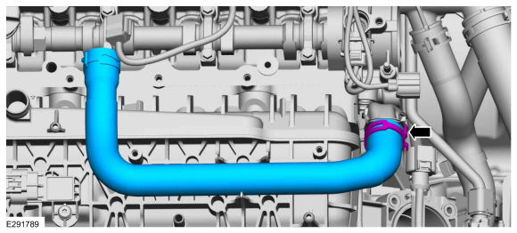
- Install the intake manifold bracket and bolts.
Torque:
Cylinder head bolt: 159 lb-in (18 N·m)
Intake manifold bolt: 89 lb-in (10 N·m)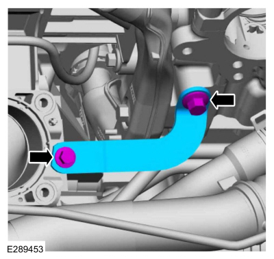
- Install the TB (throttle body).
Refer to: Throttle Body (303-04A Fuel Charging and Controls — 1.5 L EcoBoost (118 kW/160 L hp) — I4, Removal and Installation). - Lubricate the coolant outlet port O-ring with clean coolant.
Material: Motorcraft® Orange Concentrated Antifreeze/Coolant / VC-3-B (WSS-M97B44-D)
- Reinstall the coolant outlet port and install the stud.
Torque: 44 lb-in (5 N·m)
- Install the nut.
Torque: 159 lb-in (18 N·m)

- Reinstall the coolant outlet port and install the stud.
- Install and connect the coolant hose.
Use common equipment: hose clamp removal and installation tool.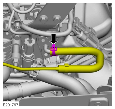
- Install a new TC mounting gasket and studs.
Torque: 89 lb-in (10 N·m)
- Install the TC nuts.
Torque:
Step 1: 62 lb-in (7 N·m)
Step 2: 124 lb-in (14 N·m)
Step 3: 17 lb-ft (23 N·m)
- Lubricate the new O-rings with clean engine oil.
Material: Engine Oil — SAE 5W-20 — Synthetic Engine Oil / XO-5W20-Q1SP (WSS-M2C945-B1)
- Install the new TC oil feed pipe assembly.
Torque: 19 lb-ft (26 N·m)
NOTICE: When installing the oil feed pipe, the sleeve on the oil feed pipe must be fully seated into the cylinder head with both O-rings inserted before the fasteners are tightened.
Position the oil feed pipe and install the bolt.
Torque: 89 lb-in (10 N·m)
- Install the turbocharger heat shield and bolts.
Torque: 89 lb-in (10 N·m)
- Install the new turbocharger coolant tube O-rings and lubricate them with clean engine coolant.
Material: Motorcraft® Orange Concentrated Antifreeze/Coolant / VC-3-B (WSS-M97B44-D)
- Reinstall the TC coolant tubes and install the bolt.
Torque: 89 lb-in (10 N·m)
- Install the turbocharger coolant tube bolt.
Torque: 17 lb-ft (23 N·m)
- Install the turbocharger coolant tube bolt.
Torque: 97 lb-in (11 N·m)

- Install the turbocharger coolant tube bolt.
- Connect the clip to the coolant tube bracket.

- Attach the wiring harness retainers.

- Reinstall the coolant hoses and connect the quick-connect couplings.

- Connect the TB (throttle body) electrical connector and the wiring harness clip.

- Connect the KS electrical connector.
- Connect the KS electrical connector.
- Reinstall and connect the coolant hose.

- Connect the IAT sensor electrical connector and the wiring harness clip.

- Reinstall the wiring harness and attach the wiring harness clip. Install the wiring harness bolt.
Torque: 89 lb-in (10 N·m)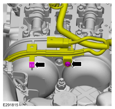
- Connect the electrical connector and attach the wiring harness clip.
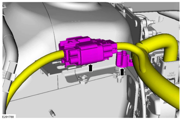
- Connect the PCM electrical connector.
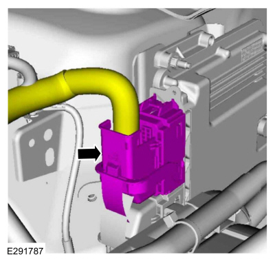
- Install the following components:
- Install the brake vacuum pump.
Refer to: Brake Vacuum Pump — 1.5 L EcoBoost (118 kW/160 L hp) — I4 (206-07 Power-Assisted Brake Actuation, Removal and Installation). - Install the high-pressure fuel pump drive block.
Refer to: High-Pressure Fuel Pump Drive Block (303-04A Fuel Charging and Controls — 1.5 L EcoBoost (118 kW/160 L hp) — I4, Removal and Installation).
- Install the brake vacuum pump.
- Connect the CHT sensor electrical connector and install the cover.

- Connect the electrical connectors to the bracket.
- Connect the turbocharger vacuum hose and clamps.
Use common equipment: hose clamp removal and installation tool.

- If equipped, install the heat shield and retainers.

- Connect the crankshaft position sensor electrical connector and the wiring harness clips.

- Tighten the coolant pump pulley bolts.
Torque: 18 lb-ft (24 N·m)
- Install the engine plug bolt.
Torque: 177 lb-in (20 N·m)
- Position the half shaft bearing bracket and install the bolts.
Torque: 35 lb-ft (48 N·m)
- Install the half shaft bearing bracket clamp and lock nuts.
Torque: 44 lb-in (5 N·m)
- Tighten the nut.
Torque: 18 lb-ft (25 N·m)
- Tighten the nut.
Torque: 18 lb-ft (25 N·m)

- Install the half shaft bearing bracket clamp and lock nuts.
- Remove and discard the engine oil filter.
Use common equipment: oil drain equipment.
Use general equipment: strap wrench.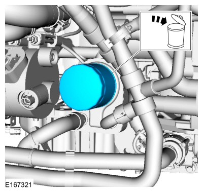
- Remove the drain plug, drain the engine oil, and install the drain plug.
Use common shop equipment: oil drain equipment
Torque: 21 lb-ft (28 N·m)
- Lubricate the O-ring seal and install a new engine oil filter.
Material: Engine oil — SAE 5W-20 — synthetic engine oil / XO-5W20-Q1SP (WSS-M2C945-B1)
Torque: 133 lb-in (15 N·m)
- Install the underbody shield and clips.

- Install the EVAP canister purge valve.
Refer to: Fuel Vapor Management Valve (303-13A Evaporative Emission Control — 1.5 L EcoBoost (118 kW/160 L hp) — I4, Removal and Installation).
- Install the CAC inlet tube.
Refer to: Charge Air Cooler (CAC) Inlet Tube (303-12A Intake Air Distribution and Filtering — 1.5 L EcoBoost (118 kW/160 L hp) — I4, Removal and Installation).
- Install the EVAP canister purge valve.
- Fill the engine with clean engine oil.
Material: Engine Oil - SAE 5W-20 - Synthetic Engine Oil / XO-5W20-Q1SP (WSS-M2C945-B1)
- Connect the battery ground cable.
Refer to: Battery Disconnect and Connect (414-01 Battery, Mounting and Cables, General Procedures). - Fill and bleed the cooling system.
Refer to: Engine Cooling System Draining, Vacuum Filling and Air Bleeding (303-03A Engine Cooling — 1.5 L EcoBoost (118 kW/160 L hp) — I4, General Procedures).
Test yourself
A quick Ford Fusion quiz: every answer comes with an explanation and a link to the manual page.