Powertrain
Valve Clearance Adjustment - General Procedures
In this manual: Powertrain
25steps
~150min
4/5difficulty
Done 0 of 25
Special Service Tools / General Equipment
| Feeler gauge | |
| Heat gun | |
| Hose Clamp Removal/Installation Tool |
Materials
| Name | Specification |
|---|---|
| Flange Sealant CU7Z-19B508-A |
WSS-M2G348-A11 |
| Engine Oil — SAE 5W-20 — Semi-Synthetic Engine Oil XO-5W20-Q1SP |
WSS-M2C945-B1 |
Check
- Position the vehicle in NEUTRAL on the lift.
Refer to: Jacking and Lifting - Overview (100-02 Jacking and Lifting, Description and Operation). - Remove the following components:
- Remove the valve cover.
Refer to: Valve Cover (303-01A Engine – 1.5 L EcoBoost (118 kW/160 L PS) – I4, Removal and Installation). - Remove the high-pressure fuel pump drive block.
Refer to: High-Pressure Fuel Pump Drive Block (303-04A Fuel Charging and Controls – 1.5 L EcoBoost (118 kW/160 L PS) – I4, Removal and Installation). - Remove the upper air cleaner outlet tube.
Refer to: Air Cleaner Outlet Tube (303-12A Intake Air Distribution and Filtering – 1.5 L EcoBoost (118 kW/160 L PS) – I4, Removal and Installation). - Remove the air cleaner.
REFER TO: Air Cleaner Element (303-12A Intake Air Distribution and Filtering - 1.5 L EcoBoost (118 kW/160 L PS) - I4, Removal and Installation).
- Remove the valve cover.
- Disconnect the electrical connector and the wiring harness retainer.
- Disconnect the coupling and remove the PCV hose.
- Disconnect and position the brake system vacuum hose aside.
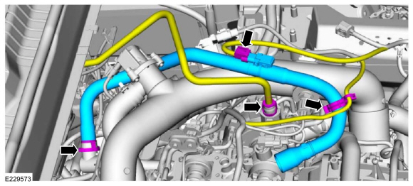
- Disconnect the wiring harness retainers and disconnect the electrical connectors.
- Disconnect the TC bypass hose.
- Loosen the clamps, remove the bolt and the TC outlet pipe.
Use common service equipment: hose clamp removal/installation tool.
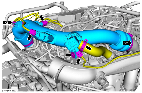
- Disconnect the electrical connector and the wiring harness retainer.

- Remove the nuts and bracket, and position the EVAP canister purge valve aside.

- Remove the retainer and disconnect the vacuum hose.
- Remove the studs and the vacuum pump. Discard the studs.

- Remove and discard the vacuum pump gasket.

- Remove the bolts and the support bracket.
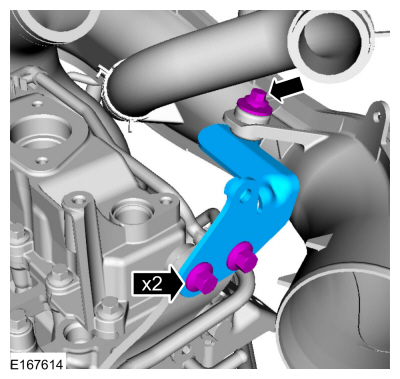
- Remove the engine cover stud.
- Remove the bolts and the stud.
- Heat and break the adhesive bond, remove the brake vacuum pump cover.
Use common equipment: heat gun.
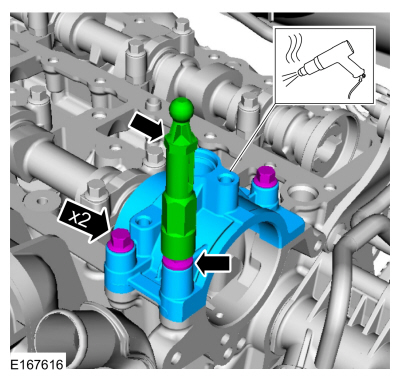
- Remove the bolts and the engine lift bracket.

NOTICE: Use only hand tools when removing or installing the spark plug, otherwise damage to the cylinder head or spark plug may occur.
Remove the spark plugs.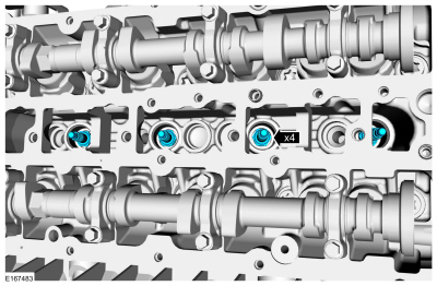
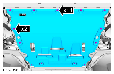
- Remove the retainers and the lower engine splash shield.
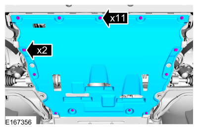
- Measure and record the clearance of each valve.
Use common equipment: feeler gauge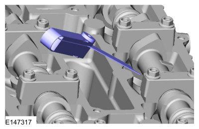
- Intake: 0.0112 in (0.285 mm)
- Exhaust: 0.0167 in (0.425 mm)
- Intake: 0.009–0.013 in (0.24–0.33 mm)
- Exhaust: 0.015–0.019 in (0.38–0.47 mm)
Adjustment
- Remove the camshafts.
Refer to: Camshafts (303-01A Engine – 1.5 L EcoBoost (118 kW/160 L PS) – I4, Removal and Installation). - Select the tappets using this formula: tappet thickness = measured clearance + existing tappet thickness - nominal clearance.
- Install the correct valve tappet.
- Install a new O-ring.
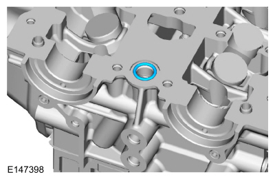
- Apply a 2.0 mm bead of flange sealant.
Material: Flange Sealant / CU7Z-19B508-A (WSS-M2G348-A11)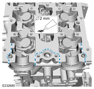
- Install the camshafts in approximately the valve overlap position for cylinder No. 4. Install the camshaft caps and tighten the bolts evenly, one-half turn at a time, until the camshaft bearing caps and the VCT bridge seat on the cylinder head.
Material: Engine Oil – SAE 5W-20 – Synthetic Engine Oil / XO-5W20-Q1SP (WSS-M2C945-B1)
Torque:
Step 1: 1 - 16: 62 lb-in (7 N·m)
Step 2: 17 - 20: 89 lb-in (10 N·m)
Step 3: 1 - 16: 45°
Step 4: 17 and 18: 70°
Step 5: 19 and 20: 53°
- Rotate the crankshaft back 45° (counterclockwise).
- Rotate the camshafts to measure the valve clearance,
- Repeat the procedure as necessary until all valve clearances meet specifications.
- Rotate the crankshaft clockwise until it stops against the special tool.
NOTICE: Use only hand tools when removing or installing the spark plug, otherwise damage to the cylinder head or spark plug may occur.
Install the spark plugs.
Torque: 115 lb-in (13 N·m)
- Install the camshaft seals.
Refer to: Camshaft Seal (303-01A Engine – 1.5 L EcoBoost (118 kW/160 L PS) – I4, Removal and Installation). - Install the engine shield and clips.
Test yourself
A quick Ford Fusion quiz: every answer comes with an explanation and a link to the manual page.
Was this page helpful?