Be careful not to damage parts located under the vehicle (floor under cover, fuel filter, fuel tank, and canister) when lifting the vehicle with a lift. (Refer to General Information - Jack Lifting Points and Support Points)
When removing the high-pressure fuel pump, high-pressure fuel line, delivery pipe and injector, there is a risk of injury from high-pressure fuel leakage. Therefore, do not attempt to perform repairs immediately after stopping the engine.
Use fender covers to avoid damaging painted surfaces.
To prevent damage, carefully disconnect the wiring connectors while holding the connector housing.
Label all wires and hoses to avoid incorrect connection.
Remove the engine cover. (Refer to Engine and Transaxle Assembly - "Engine Cover")
Remove the engine compartment cover. (Refer to Engine and Transaxle Assembly - "Engine Compartment Under Cover")
Drain the engine coolant. (Refer to Cooling System - "Engine Coolant")
Drain the engine oil. (Refer to Lubrication System - "Engine Oil")
Remove the air cleaner assembly. (Refer to Air Intake and Exhaust System - "Air Cleaner").
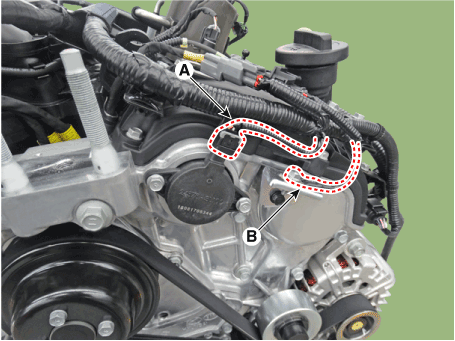
Disconnect the variable force solenoid (VFS) valve connector (A) and ground cable (B).
Remove the expansion tank. (Refer to Intake and Exhaust System - "Expansion Tank")
Remove the LH/RH cylinder head cover. (Refer to Cylinder Head Assembly - "Cylinder Head Cover").
Remove the drive belt. (Refer to Valve Timing System - "Drive Belt")
Remove the idler pulley. (Refer to Valve Timing System - "Idler Pulley")
Remove the drive belt tensioner. (Refer to Valve Timing System - Drive Belt Tensioner)
Remove the crankshaft damper pulley. (Refer to Valve Timing System - "Crankshaft Damper Pulley")
Remove the water pump. (Refer to Cooling System - "Water Pump").
Remove the lower oil pan. (Refer to Lubrication System - "Oil Pan").
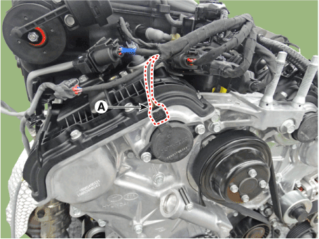
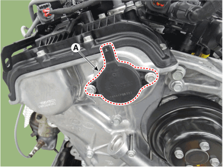
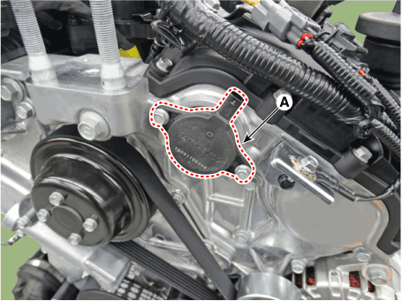
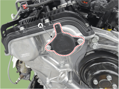
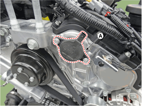
Remove the right and left variable force solenoid (VFS) valves (A). [Right][LH]
The variable force solenoid (VFS) must be removed before removing the timing chain cover.
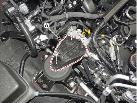
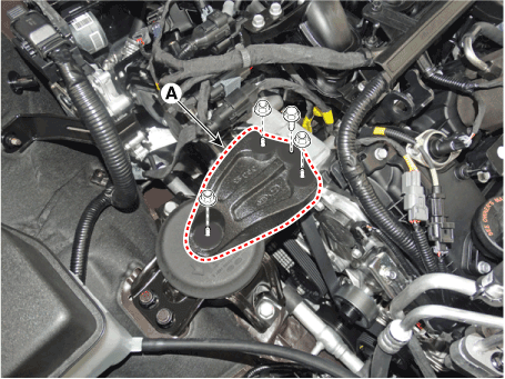
Remove the engine mount support bracket.
Place a jack on the edge of the upper oil pan to support the engine.
Insert a rubber block between the jack and the upper oil pan.
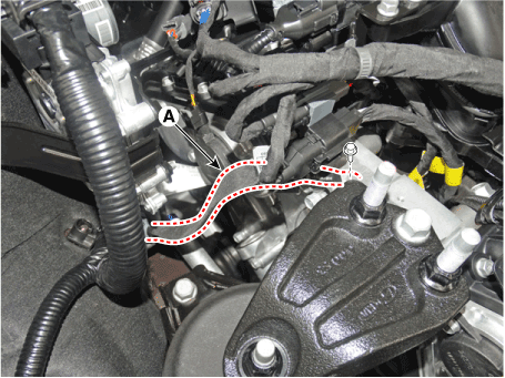
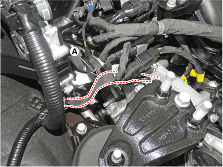
Disconnect the engine ground cable (A).
Remove the engine mount support bracket (A).
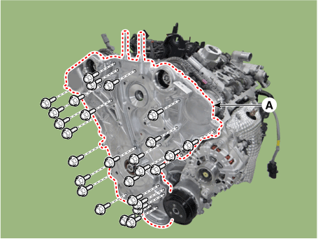
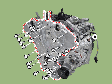
Remove the timing chain cover (A).
Be careful not to damage the mating surfaces of the cylinder block, cylinder head and timing chain cover.
Installation
Install the timing chain cover.
The sealant areas on the chain cover and mating parts (cylinder head, cylinder block and oil pan) must be free of engine oil, etc.
Before installing the timing chain cover, apply liquid gasket TB 1217H to the joint between the cylinder head and the cylinder block. Assemble the parts within 5 minutes after applying the sealant.
Bead width: 4.0 mm (0.2 in)
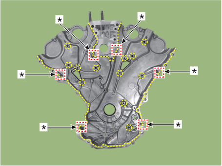
Apply liquid gasket TB 1217H to the timing chain cover. Assemble the parts within 5 minutes after applying the sealant. Apply the sealant in a continuous bead.
Fill six (6) T-joints with sealant.
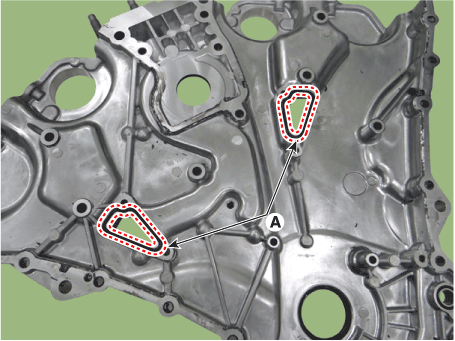
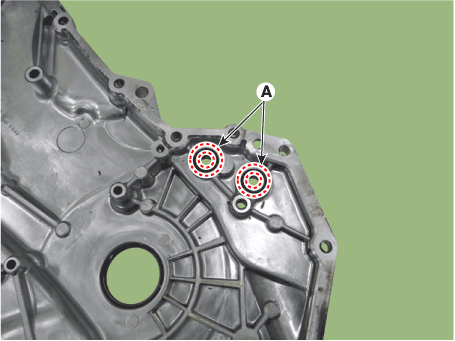
Apply sealant around two (2) dowel pin holes.
Install a new gasket (A) to the timing chain cover.
When installing the timing chain cover, be careful not to disturb the sealant applied to the timing chain cover so that it does not contact other parts.
Install a new O-ring (A).
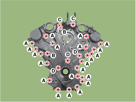
Use the locating dowel pins on the cylinder block and the holes in the timing chain cover (A) as guides to position the timing chain cover correctly. Tightening torque A (21 pcs): 18.6–22 N·m B (2 pcs): 24.5–26 N·m C (2 pcs): 58.8–69 N·m D (3 pcs): 9.8–11.8 N·m
Do not start the engine or perform a pressure test for 30 minutes after assembly.
Install the engine mount bracket.
Install the engine mount bracket (A).
Tightening torque: 98.1 - 118 N·m
Connect the engine ground cable (A).
Remove the jack from the upper oil pan.
Install the right and left variable force solenoid (VFS) valves (A).
Tightening Torque: 9.8–11.8 N·m
[RH][LH]
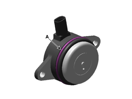
Do not use a dropped variable force solenoid (VFS) valve.
Observe the following precautions when installing the variable force solenoid (VFS) valve.
After replacing the O-ring (A) of the variable force solenoid (VFS) valve, apply engine oil to the new O-ring (A).
Push the variable force solenoid (VFS) valve until it contacts the timing chain cover, then temporarily tighten the bolt.
Tighten the variable force solenoid (VFS) valve to the specified torque.
Install the remaining parts in the reverse order of removal.
Fill the engine oil.
Clean the battery terminal posts and cable clamps with sandpaper. Assemble, then apply grease to prevent corrosion.
Inspect for fuel leaks.
After assembling the fuel line, turn the ignition switch ON (do not start the engine) to operate the fuel pump for about 2 seconds and pressurize the fuel line.
Repeat this operation two or three times, then check for fuel leaks at all points of the fuel line.
Fill the radiator and the coolant reservoir with engine coolant.
Bleed air from the cooling system.
Start the engine and let it run until it warms up (until the radiator fan operates 3 or 4 times).
Stop the engine and let it cool down. Check the coolant level in the radiator and add coolant if necessary. This will allow trapped air to be bled from the cooling system.
Securely install the radiator cap, then restart the engine and check for leaks.
?
Test yourself
A quick Hyundai Palisade quiz: every answer comes with an explanation and a link to the manual page.