ESC Control Module
Components and Component Location
Components
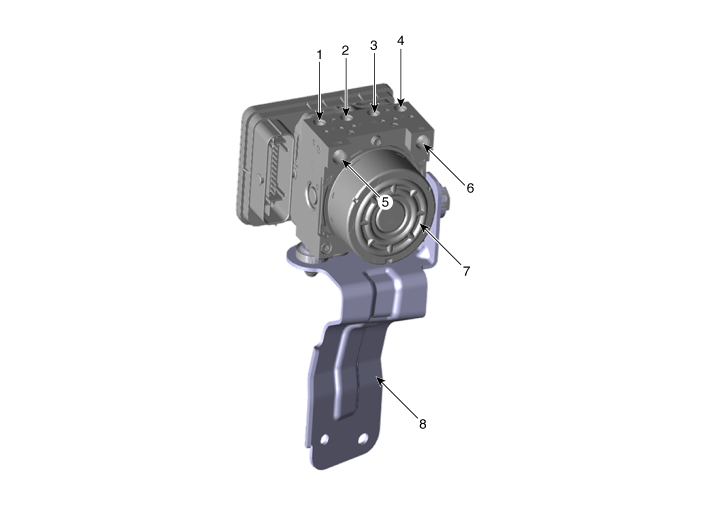
| 1. Front right tube 2. Rear left tube 3. Rear right tube 4. Front left tube |
5. Front LH Wheel Speed Sensor 6. Front RH Wheel Speed Sensor 7. ESC Control Module (HECU) 8. Bracket |
Repair Procedures
Removal
Turn the ignition switch OFF and disconnect the negative (-) battery cable.
Remove the brake fluid from the master cylinder reservoir using a syringe.
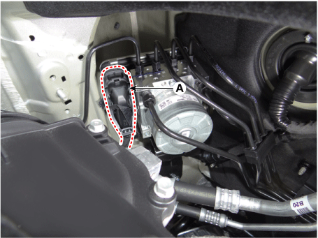
Pull up the ESC connector lock (A), then disconnect the connector.
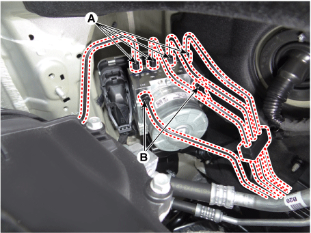
Disconnect the brake tubes from the ESC by turning the nuts counterclockwise with a wrench.
Tightening torque:
A: 13,7–16.7 N·m
B: 18,6–23 N·m
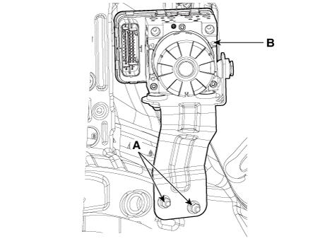
Loosen the ESC bracket nuts (A), then remove the ESC and bracket.
Tightening torque: 16.7–26 N·m
Installation
Install in the reverse order of removal.
After installation, bleed the brake system.
(Refer to Brake System - "Brake Bleeding Procedures")
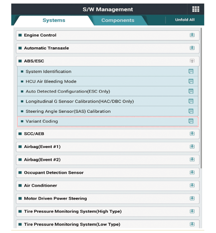
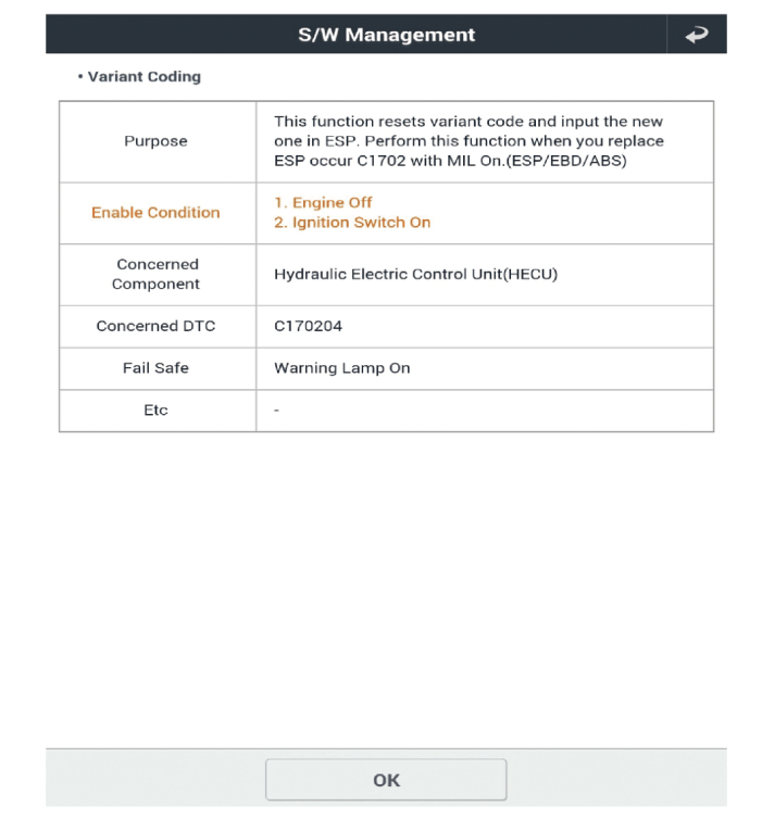
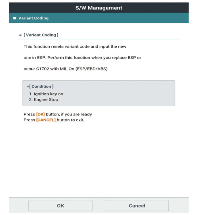
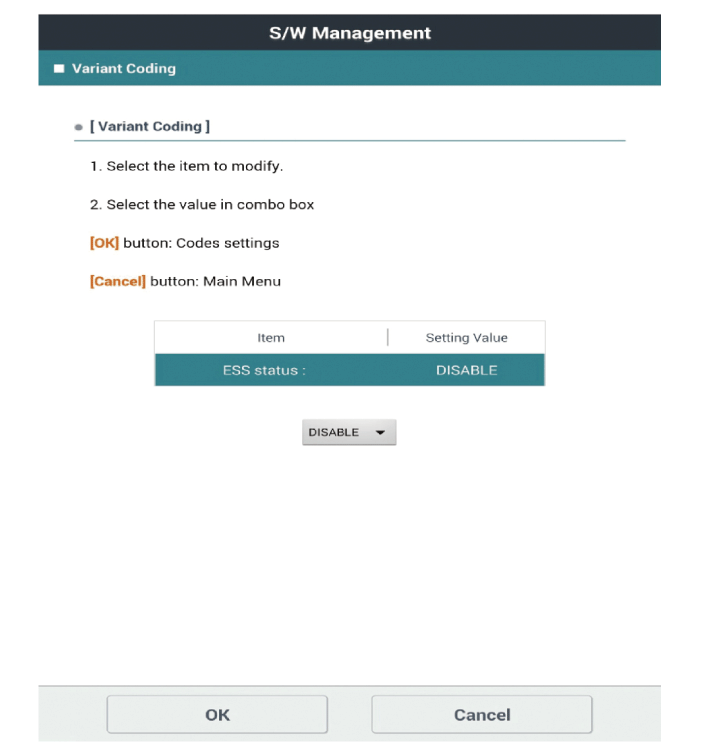
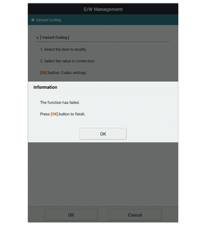
Perform variant coding.
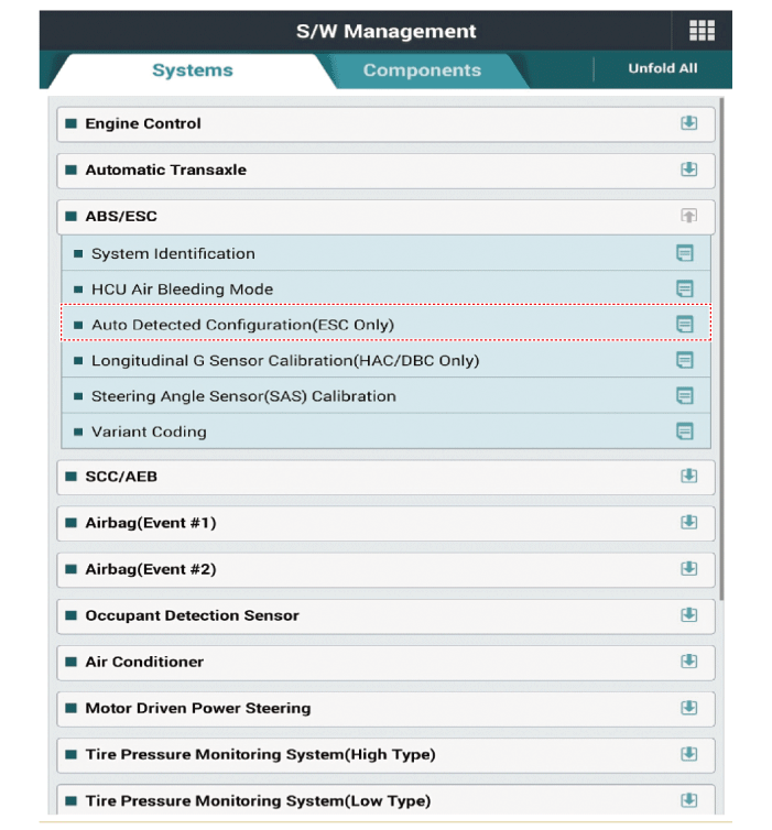
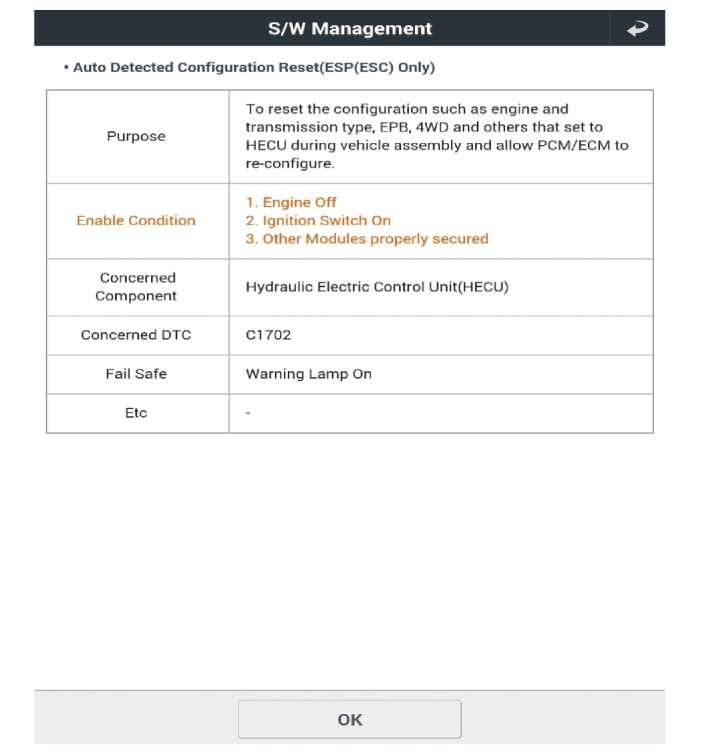
Perform automatic sensor calibration.
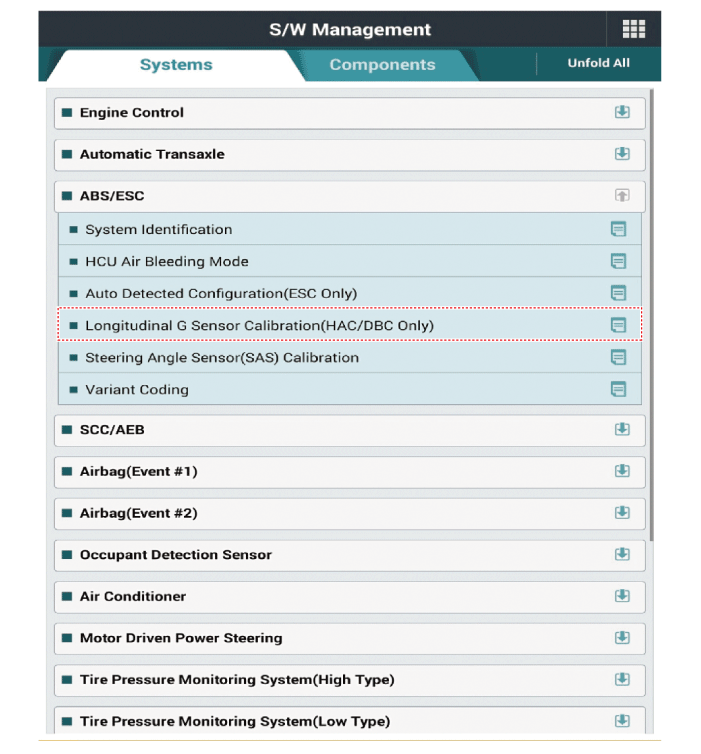
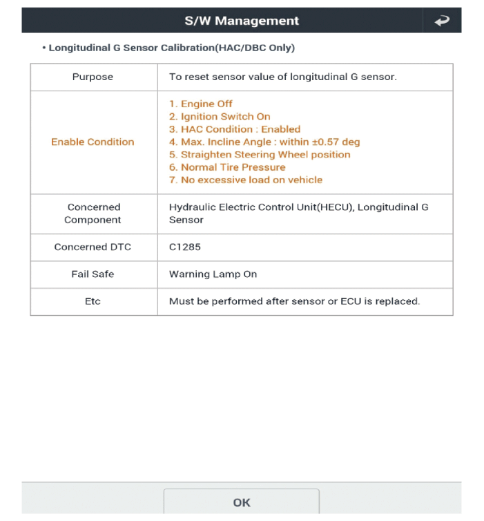
Perform longitudinal acceleration sensor calibration.
Diagnostic Procedure Using the Diagnostic Tool
Perform the diagnostic procedure using the diagnostic device as shown below:
Connect the self-diagnosis connector (16-pin) located under the driver's side instrument panel, then turn the ignition switch ON.
Select "Vehicle Model" and "ABS/ESC" on the KDS vehicle selection screen, then select OK.
[Variant Coding]
[Automatic Sensor Calibration]
[Longitudinal Acceleration Sensor Calibration]
Test yourself
A quick Kia Forte BD quiz: every answer comes with an explanation and a link to the manual page.