Rear Axle with Torsion Beam
Components and Component Location
Components
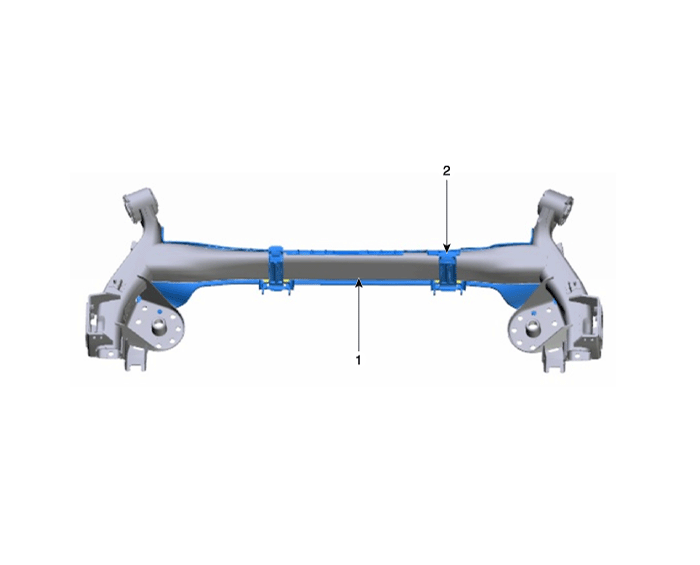
| 1. Torsion Beam | 2. Torsion Beam Axle Cover |
Repair Procedures
Removal and Installation
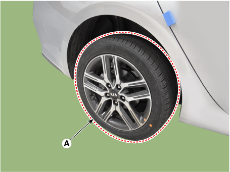
Remove the rear wheel and tire (A).
Tightening torque: 107.9–128 N·m
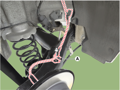
Disconnect the rear wheel speed sensor bracket (A).
Tightening torque: 8.8 - 13.7 N·m
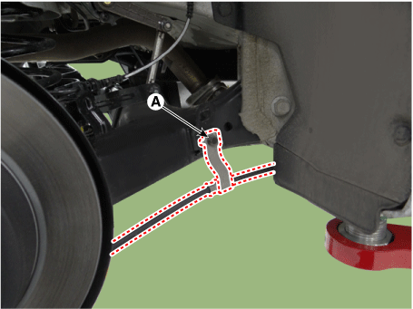
Disconnect the parking brake cable bracket (A).
Tightening torque: 8.8 - 13.7 N·m
Remove the rear hub bearing assembly.
(Refer to Driveshaft and Axle — Rear Hub — Carrier)
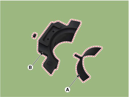
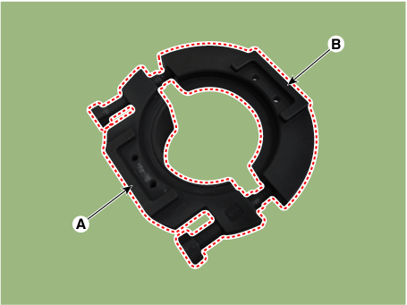
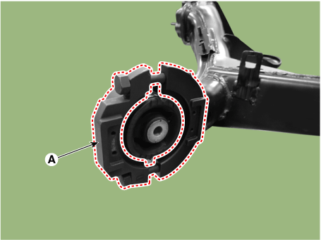
Remove the torsion beam axle under the cover (A).
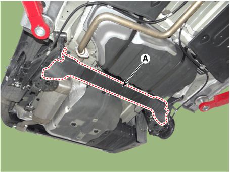
Support the jack under the torsion beam axle (A).
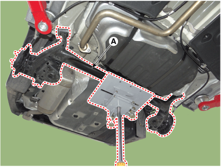
Loosen the lower mounting bolt and remove the rear shock absorber (A).
Tightening torque: 98.0–118 N·m
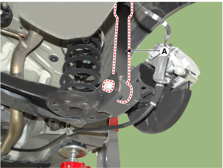
Remove the coil spring (A).
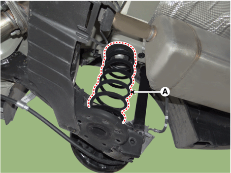
Remove the torsion beam axle mounting bolts (A).
Tightening torque: 156.9–176 N·m
[RH]
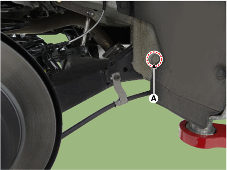
[LH]
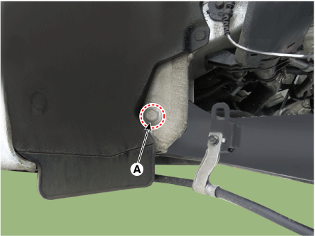
Remove the torsion beam axle (A).
Install in the reverse order of removal.
Check the wheel alignment.
(Refer to Rear Suspension System — Rear Wheel Alignment)
Replacement
CTBA Bushing (Coupled Torsion Beam Axle)
Steel Type
Using SST (09551-AL100), replace the CTBA (Coupled Torsion Beam Axle) bushing.
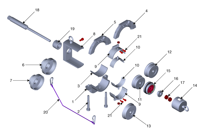
1. Beam Clamp A
2. Beam Clamp Bolt
3. Beam Clamp Adapter
4. Beam Clamp B
5. Beam Clamp C
6. Installer Adapter A
7. Installer Adapter B8. Beam Clamp Support
9. Bushing Guide A
10. Bushing Guide B
11. Remover Adapter A
12. Remover Adapter B
13. Installer Adapter C
14. Protective Cap15. Bearing
16. Bearing Washer
17. Nut
18. Main Bolt
19. Main Nut
20. Lock Wire
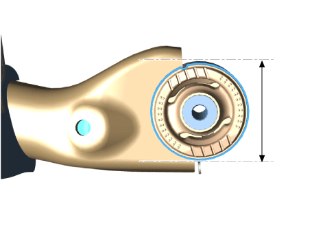
21. Bushing Guide BoltMeasure the outer diameter of the torsion beam axle.
The outer diameter of the torsion beam axle is 78 mm (3.0709 in) or 84 mm (3.3071 in), depending on the type.
Install the beam clamp adapter (A) onto beam clamp A (B).
Temporarily install beam clamp A (A) and beam clamp C (B) with the bolt.
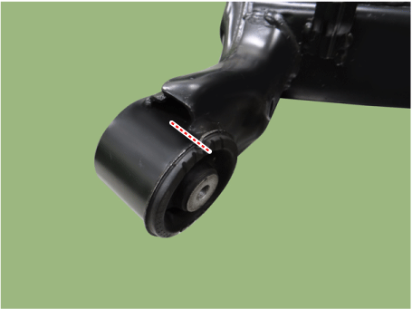
Mark the torsion beam axle to match the bushing groove.
Assemble the bolt after installing the beam clamp (A) onto the beam tube accurately.
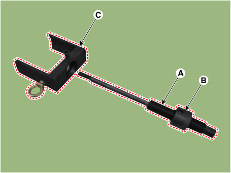
Assemble the main bolt (A) and main nut (B), then insert them into the beam clamp support (C).
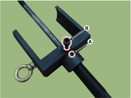
Align the hole of the main nut (A) and the bolt (B) precisely, then assemble them.
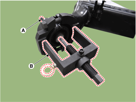
Insert the main bolt (A) into the bushing hole, then assemble the beam support (B) and the beam clamp guide, aligning them.
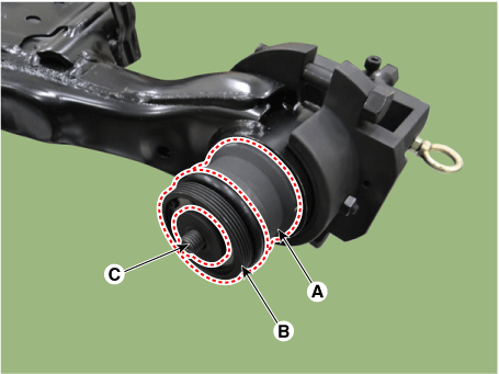
Install the remover adapter A (A), bearing (B) and washer (C) onto the main bolt in that order.
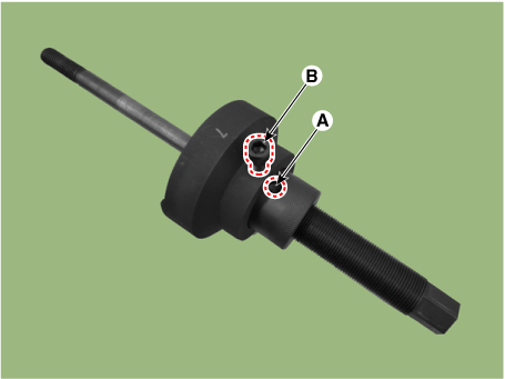
Temporarily install 2 nuts (A).
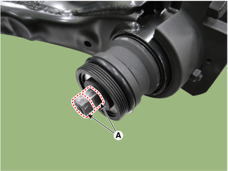
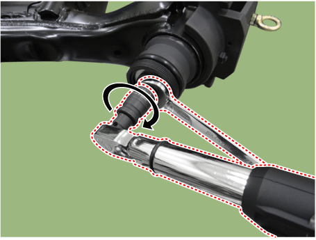
Install using the double nut method with a wrench and a torque wrench.
Tightening torque: 49 N·m
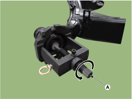
Install the SST properly by turning the main bolt (A) counterclockwise.
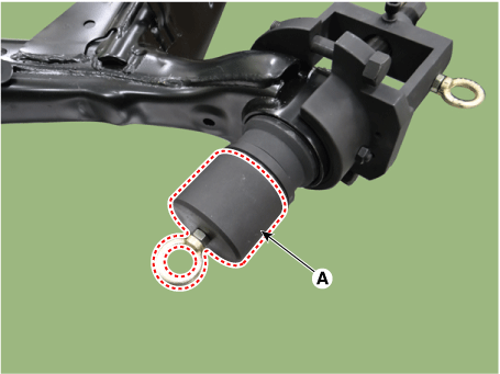
Install the protective cap (A).
Connect the lock wire (A) by wrapping it once around the torsion beam axle.
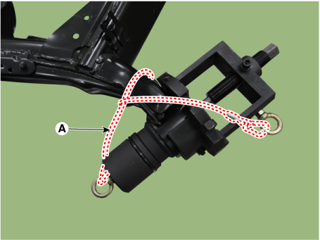
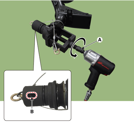
Remove the bushing by turning the main bolt (A) counterclockwise using an air impact wrench.
In this procedure, visually check through the cover hole (B) whether the nut is loosening. If the nut is loosening, tighten it to the specified torque.
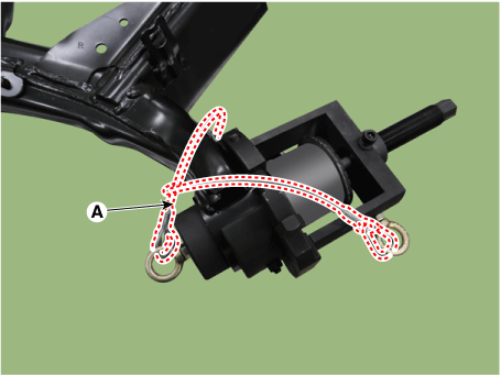
Disassemble the lock wire (A) after the bushing has been completely removed.
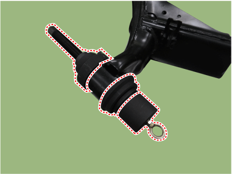
Remove the bushing and SST from the torsion beam axle.
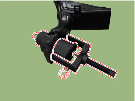
Remove the bushing (A) by disassembling the SST.
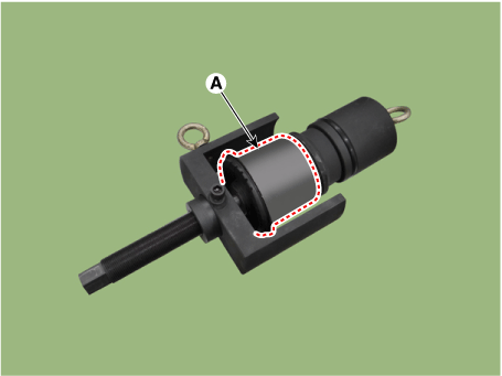
Remove the beam clamp (A) from the torsion beam axle.
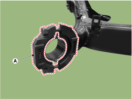
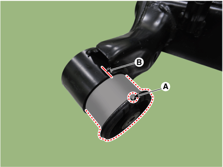
Install the bushing after aligning the mark on the new bushing with the mark on the torsion beam axle.
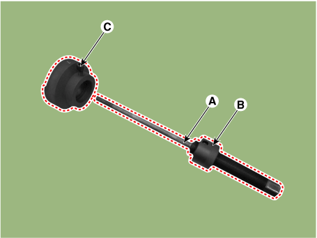
Assemble the main bolt (A) and main nut (B), then insert them into the Installer Adapter B (C).
Precisely align the hole of the main nut (A) and the bolt (B), then assemble them.
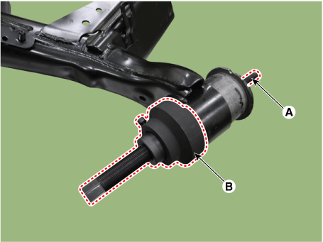
Install the installer adapter (B) by inserting the main bolt (A) into the bushing hole.
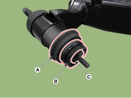
Install it onto the main bolt in the order of installer adapter C (A), bearing (B) and washer (C).
Pre-install the two nuts (A).
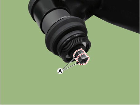
Install using the double nut method with a wrench and a torque wrench.
Tightening torque: 49 N·m
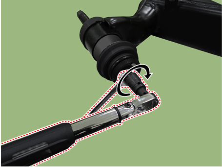
Install the SST properly by turning the main bolt (A) counterclockwise.
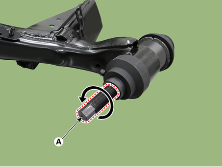
Install the protective cap (A).
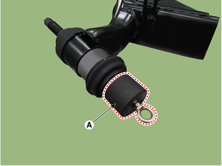
Connect the lock wire (A) by wrapping it once around the torsion beam axle.
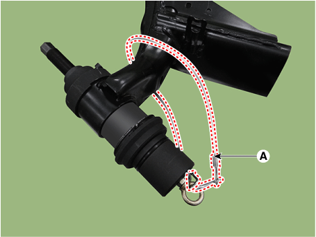
Install until a 5 mm (0.1969 in) gap remains between the bushing and the torsion beam, turning the main bolt (A) counterclockwise with an air impact wrench.
In this procedure, visually check through the cover hole (B) whether the nut is loosening. If the nut is loosening, tighten it to the specified torque.
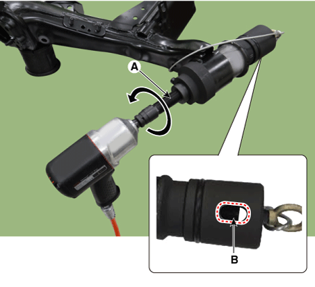
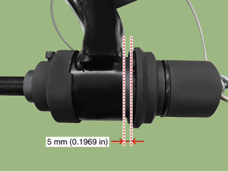
Turn the main bolt counterclockwise until the bushing and the end of the torsion beam are fitted together, using a hand wrench.
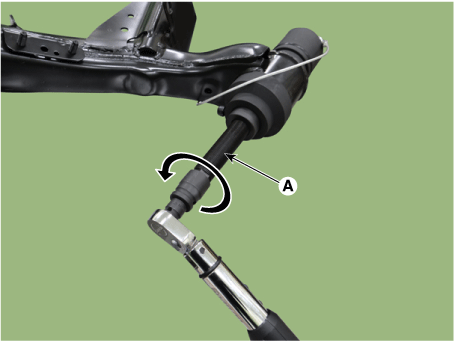
Release the pressurized tools by turning the main bolt (A) clockwise after the bushing is fully installed.
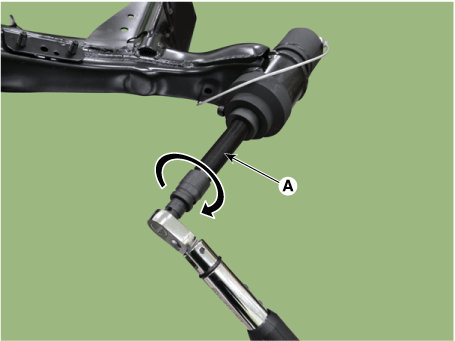
Remove the lock wire (A).
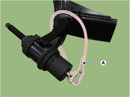
Remove the SST from the torsion beam axle.
Test yourself
A quick Kia Forte BD quiz: every answer comes with an explanation and a link to the manual page.