Brake System
Vacuum Pump
In this manual: Brake System
9steps
~54min
2/5difficulty
Done 0 of 9
Components and Component Location
Components
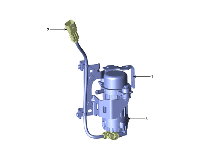
| 1. Vacuum Pump Bracket 2. Vacuum Connector |
3. Vacuum Pump |
Circuit Diagrams
Wiring Diagram
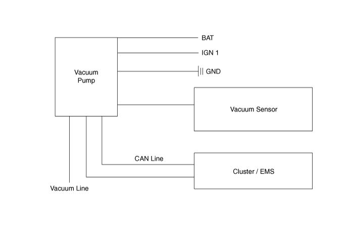
Terminal Function
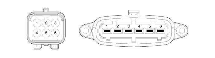
| PIN No. | Function | Wire Color |
| 1 | Ground | BLACK |
| 2 | CAN High | WHITE |
| 3 | CAN Low | YELLOW |
| 4 | Vacuum Sensor | PINK |
| 5 | IGN 1 | BLUE |
| 6 | Battery (+) | BLUE |
Repair Procedures
Removal and Installation
Disconnect the negative battery cable.
Disconnect the vacuum pump connector (A).
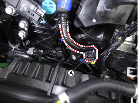
Remove the air duct and air cleaner assembly.
G 1.6 T-GDI GAMMA (Refer to Engine Mechanical System - "Air Cleaner")
Disconnect the RCV solenoid valve connector (A) and the boost pressure sensor (BPS) connector (B).
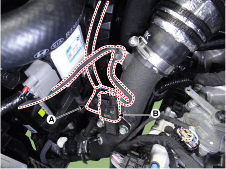
Disconnect the intercooler outlet hose (A).
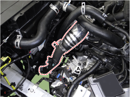
Disconnect the clamp (A) from the vacuum pump bracket.
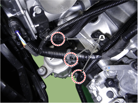
Remove the engine room cover.
G 1.6 T-GDI GAMMA (Refer to Engine Mechanical System - "Engine Room Cover")
Disconnect the vacuum hose (A), then remove the vacuum pump (B).
Tightening torque: 19.6 - 29 N·m
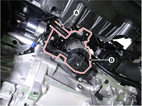
Install in the reverse order of removal.
Test yourself
A quick Kia Forte BD quiz: every answer comes with an explanation and a link to the manual page.
Was this page helpful?