Rear Drum Brake
Components and Component Location
Components
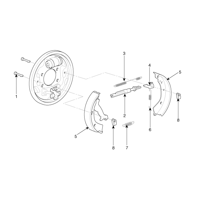
| 1. Shoe hold-down pin 2. Shoe adjuster 3. Upper return spring 4. Adjusting lever |
5. Shoe 6. Adjusting spring 7. Lower return spring 8. Shoe hold-down spring |
Repair Procedures
Removal
Release the parking brake.
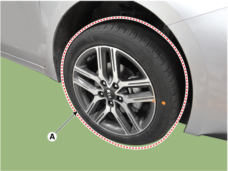
Remove the rear wheel and tire (A).
Tightening torque: 107.9–128 N·m
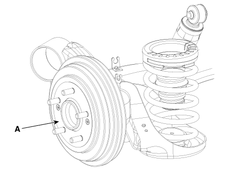
Remove the rear brake drum (A).
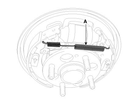
Remove the upper return spring (A).
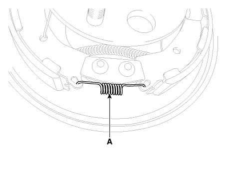
Remove the lower return spring (A).
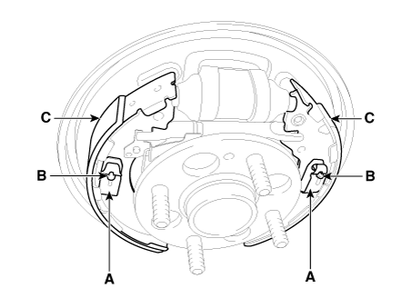
Remove the shoe hold-down springs (A) and shoe hold-down pins (B), then remove the brake shoe (C). Be careful not to damage the dust boot on the wheel cylinder.
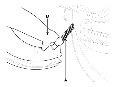
Remove the parking brake cable (A), then remove the brake shoe (B).
Disconnect the brake tubes (A) from the wheel cylinder (B).
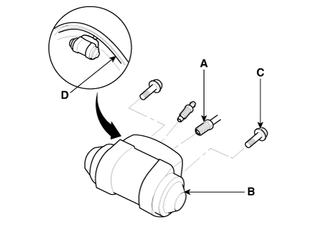
Remove the bolts (C) and the wheel cylinder (B) from the backing plate (D).
Installation
Apply sealant (C) between the wheel cylinder (B) and the backing plate (D), then install the wheel cylinder.
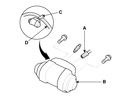
Connect the brake tubes (A) to the wheel cylinder.
Tightening torque: 12.7 - 16.7 N·m
Connect the parking brake cable (A) to the brake shoe.
Install the brake shoes (C) on the backing plate. Be careful not to damage the wheel cylinder dust boots.
Install the shoe hold-down pins (B) and the shoe hold-down springs (A).
Clean the threaded portions of the adjusting sleeve (A) and the inner part of the strut (B). Apply grease to the threads of the adjuster assembly. To shorten the brackets, turn the adjusting bolt (C).
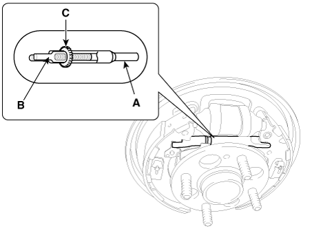
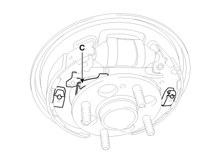
Hook the shoe adjuster lever (C), then install it on the brake shoe.
Install the adjuster assembly (B) and the upper return spring (A) in the direction shown. Be careful not to damage the wheel cylinder dust boots.
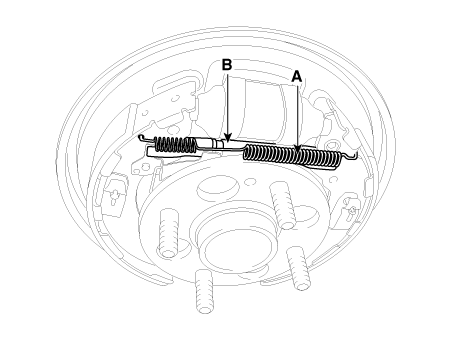
Install the lower return spring (B).
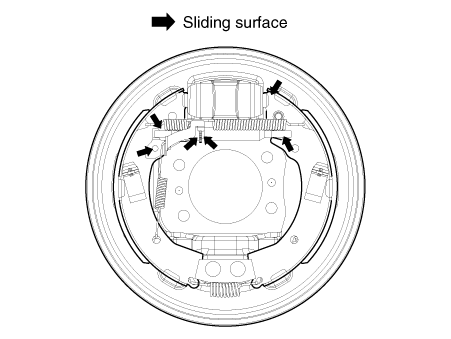
Apply brake cylinder grease or equivalent rubber grease to the guide surfaces shown. Do not allow grease to get on the brake pads.
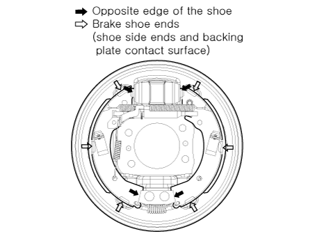
Apply brake cylinder grease or equivalent rubber grease to the shoe ends and opposite shoe edges shown. Do not allow grease to get on the brake linings.
Install the rear brake drum (A).
Tightening torque: 4.9 - 5.9 N·m
If the wheel cylinder was removed, bleed the brake system.
Depress the brake pedal several times to activate the self-adjusting brake.
Adjust the parking brake.
Inspection
Raise the rear of the vehicle and make sure it is securely supported.
Release the parking brake and remove the rear brake drum.
Inspect the wheel cylinder (A) for leaks.
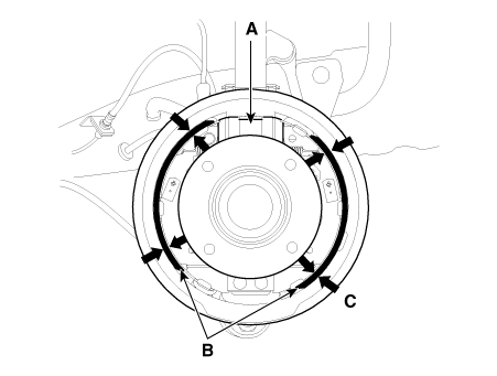
Inspect the brake shoes (B) for cracks, glazing, wear and contamination.
Measure the thickness of the brake lining (C) on the shoe.
Lining Thickness
Standard: 4.3 mm (0.1693 in.)
Service limit: 1.0 mm (0.039 in.)
If the brake lining thickness is less than the service limit, replace the brake shoes as a set.
Check the wheel hub bearings for smooth operation. If necessary, replace them.
Measure the inner diameter of the brake drum with a caliper.
Brake drum inner diameter
Standard: 203.2 mm (8.0 in.)
Service limit: 205.2 mm (8.079 in.)
Brake drum out-of-round
Maximum limit: 0.06 mm (0.00236 in.)
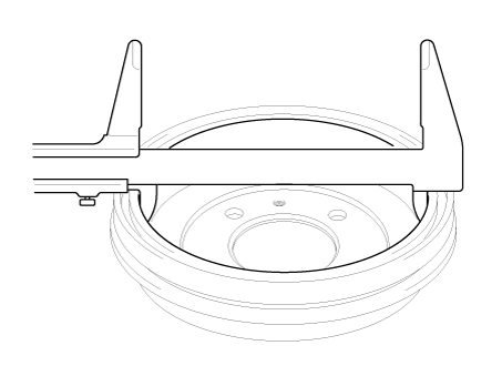
If the brake drum inner diameter exceeds the service limit, replace the brake drum.
Inspect the brake drum for scoring, grooves and cracks.
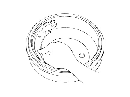
Inspect the brake shoe and drum for proper contact.
Inspect the outside of the wheel cylinder for excessive wear and damage.
Inspect the backing plate for wear or damage.
Test yourself
A quick Kia Forte BD quiz: every answer comes with an explanation and a link to the manual page.