Single-Use Parts
Front Axle Assembly
In this manual: Single-Use Parts
18steps
~108min
4/5difficulty
Done 0 of 18
Contents:
Components and Components Location
Component
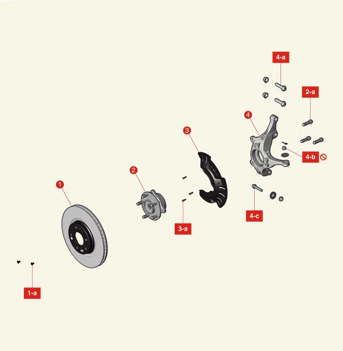
| 1. Front Brake Disc 1-a. 4.9 - 5,9 N·m (0.5 - 0.6 kgf·m, 3.6 - 4.3 lb·ft, 43.4 - 52.1 lb·in) 2. Front Hub Assembly 2-a. 78.5 - 98 N·m 3. Front Dust Cover 3-a. 7.8 - 11,8 N·m |
4. Front Knuckle 4-a. 137.3 - 157 N·m 4-b. 34.3 - 44 N·m 4-c. 58.8 - 71 N·m |
Front Hub Assembly Removal and Installation
Special Service Tool
| Tool Name / Number | Illustration | Description |
| CV joint puller 09517 - 4E000 |
 |
Used for removal of CV joint |
Removal
- Remove the front wheel and tires. (Refer to Suspension System - "Wheel")
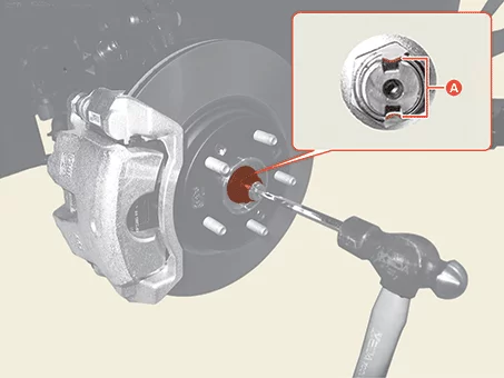
- Unlock the driveshaft lock nut caulking (A), by hammering on a chisel or suitable tool.
- Remove the front brake disc. (Refer to Brake System - "Front Brake Disc")
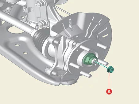
- Remove the driveshaft lock nut (A).
Tightening torque : 274.6 - 294 N·m
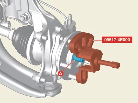
- Separate the front driveshaft (A) from the front hub assembly using the SST (09517 - 4E000).
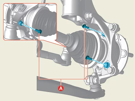
- Remove the front hub assembly bolts (A).
Tightening torque : 78.5 - 98 N·m
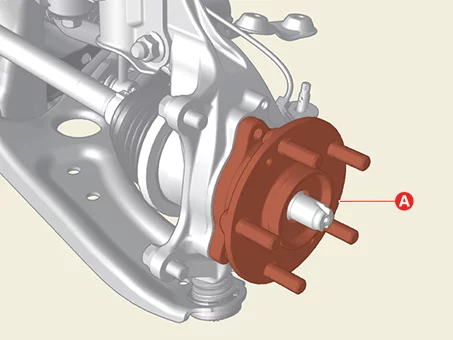
- Remove the front hub assembly (A).
Installation
- Install in reverse order of removal.

- Do not reuse the driveshaft lock nut.
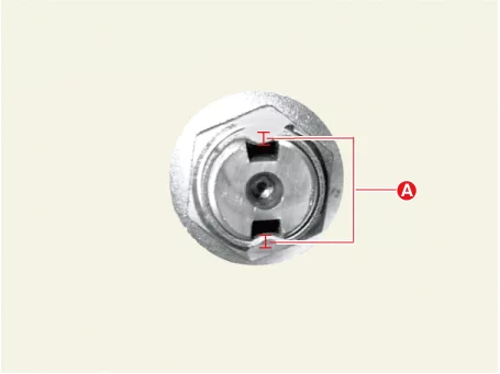
- After tightening the driveshaft lock nut, caulk the lock nut to an appropriate depth (A) by using a chisel or suitable tool.
Caulking Depth (A) : 1.5 mm (0.059 in.) or more
- Press the brake pedal to prevent the driveshaft from rotating when tightening the driveshaft lock nut.
Front Hub Assembly Inspection
Inspection
- Check the hub for cracks and spline wear.
- Check the hub bearing for defects.
Front Dust Cover Removal and Installation
Removal
- Remove the front hub assembly. (Refer to Front Axle Assembly - "Front Hub Assembly")
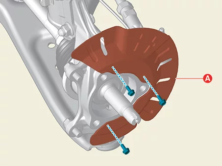
- Remove the front dust cover (A) after removing the bolts.
Tightening torque : 7.8 - 11,8 N·m
Installation
- Install in reverse order of removal.
Front Dust Cover Inspection
Inspection
- Check the front dust cover for cracks, defects.
Front Knuckle Removal and Installation
Special Service Tool
| Tool Name / Number | Illustration | Description |
| Ball joint puller 09568 - 1S100 |
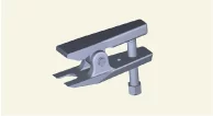 |
Used for removal of the tie rod end ball joint |
| Lower arm ball joint remover 0K545 - A9100 |
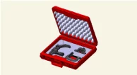 |
Used for removal of front lower arm ball joint |
Removal
- Remove the front dust cover. (Refer to Front Axle Assembly - "Front Dust Cover")
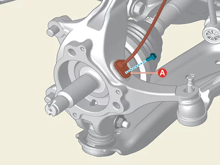
- Remove the front wheel speed sensor (A) after removing the bolt.
Tightening torque : 6.9 - 10,8 N·m
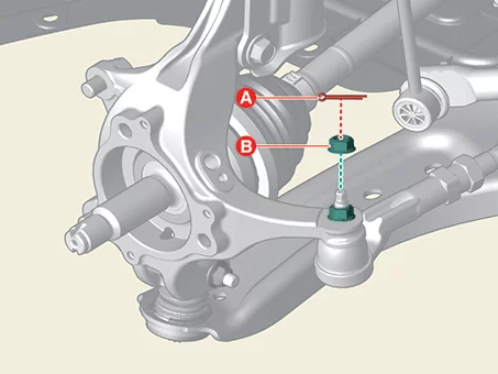
- Separate the tie rod end ball joint from the front axle.
- Remove the split pin (A).
- Remove the lock nut (B).
Tightening torque : 34.3 - 44 N·m
- Do not reuse the split pin.
- Do not reuse the lock nut.
- Be careful not to damage the boot of the link.
- Use a hand tool when removing or installing the lock nut.
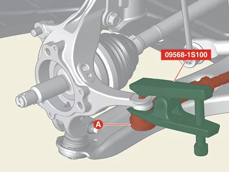
- Separate the tie rod end ball joint (A) using the SST (09568 - 1S100).
- Separate the lower arm ball joint from the front axle.
- Remove the lower arm nut (A) and bolt (B).
Tightening torque : 58.8 - 71 N·m

Fix the lower arm ball joint bolt when removing or installing the nut.
- Do not reuse the split pin.
- Be careful not to change the bolt, nut and washer installing position.
- Install the support bolt to the lower arm ball joint mounting hole, and then rotate the bolts (A).
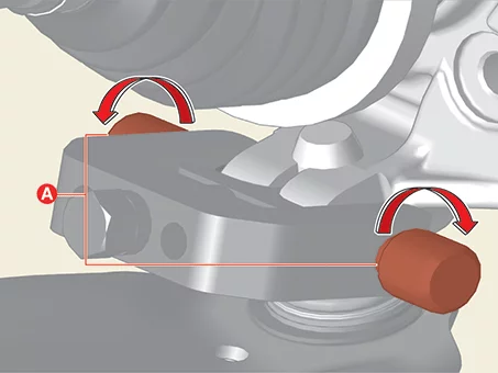
Use the support bolt (A) of the SST (0K545 - A9100).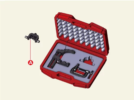
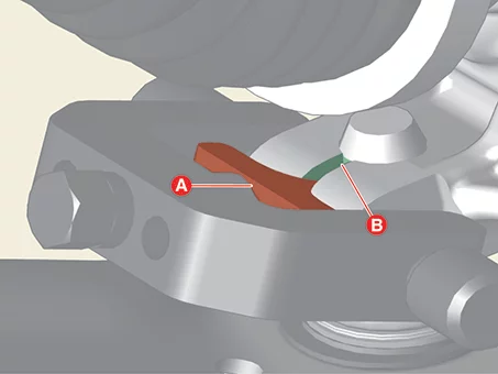
- Place the support body (A) between the lower arm and the front axle (B).
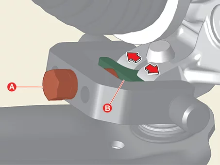
- Rotate the bolt (A) clockwise, and then insert the support body (B) to broaden the gap.
- Install the main body (A) between the front strut assembly and front lower arm.

Use the main body (A) of the SST (0K545 - A9100).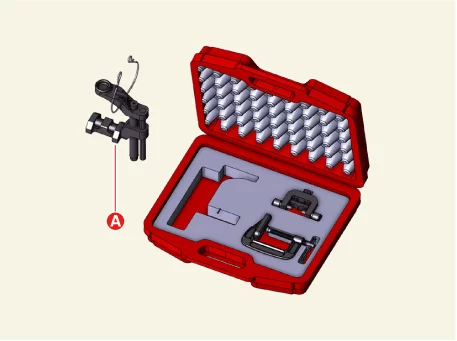
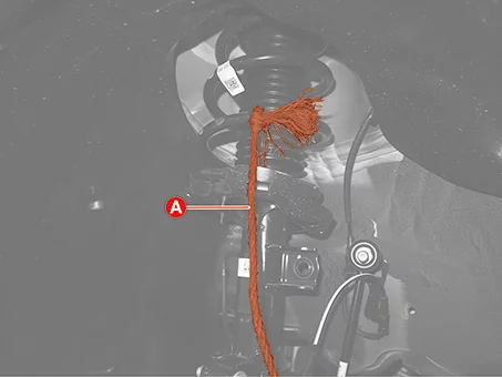
- Secure the main body with the wire (A) to prevent it from falling.

- Install the C-clamp (A) by turning the handle (B) to prevent the main body from slipping.
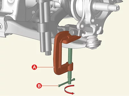
Use the C-clamp (A) of the SST (0K545 - A9100).
- Tighten the bolt (A), and then separate the front lower arm from the front axle.
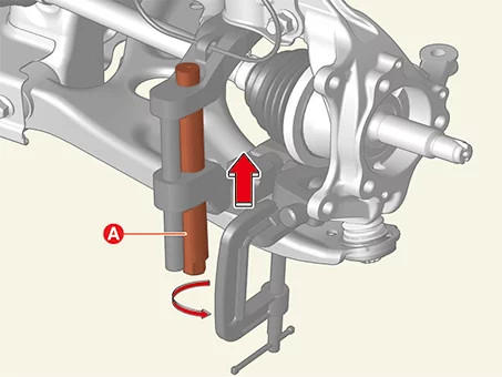
- Remove the lower arm nut (A) and bolt (B).
- Remove the front knuckle (A) after removing the bolts and nuts.
Tightening torque : 137.3 - 157 N·m

Installation
- Install in reverse order of removal.
- Check the alignment. (Refer to Suspension System - "Alignment")
Front Knuckle Inspection
Inspection
- Check the front knuckle for cracks.
Was this page helpful?