Remove the front wheel and tires. (Refer to Suspension System - "Wheel")
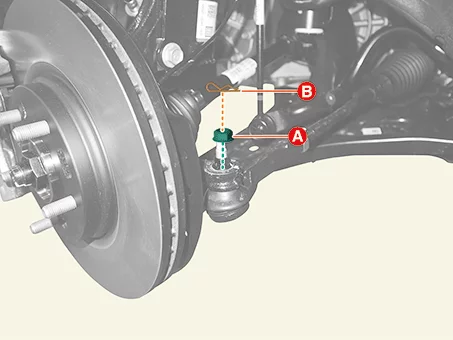
Separate the tie rod end ball joint from the front axle.
Remove the split pin (A).
Remove the lock nut (B).
Tightening torque : 34.3 - 44 N·m
Do not reuse the split pin.
Do not reuse the lock nut.
Be careful not to damage the boot of the link.
Use a hand tool when removing or installing the lock nut.
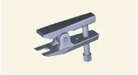
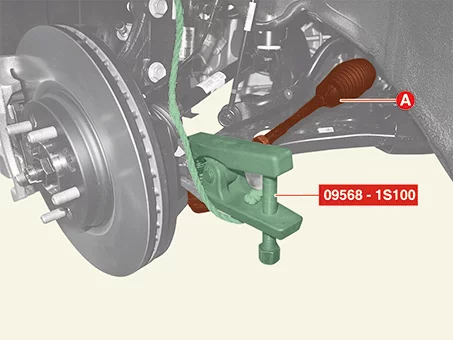
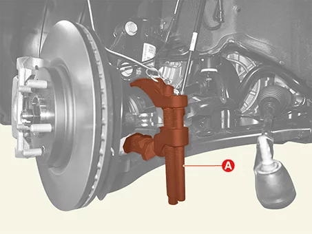
Separate the tie rod end ball joint (A) using the SST (09568 - 1S100).
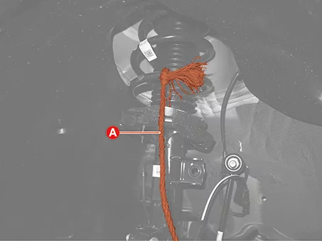
Secure the SST (09568 - 1S100) to prevent it from falling off using the wire (A).
Separate the lower arm ball joint from the front axle.
Remove the lower arm nut (A) and bolt (B).
Tightening torque : 58.8 - 71 N·m
Fix the lower arm ball joint bolt when removing or installing the nut.
Do not reuse the split pin.
Be careful not to change the bolt, nut and washer installing position.
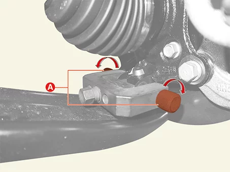
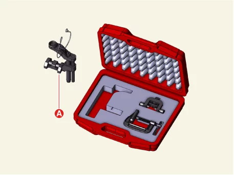
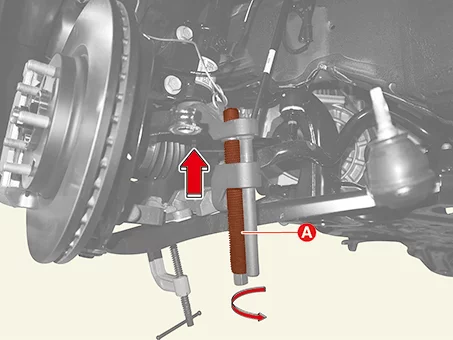
Install the support bolt to the lower arm ball joint mounting hole, and then rotate the bolts (A).
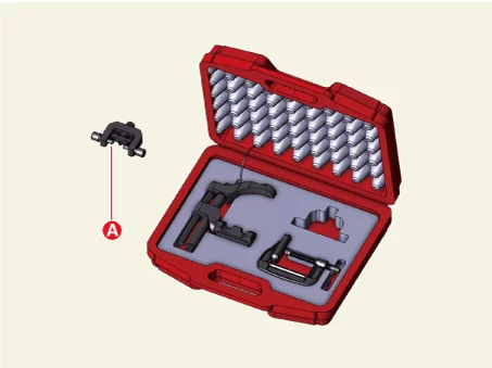
Use the support bolt (A) of the SST (0K545 - A9100).
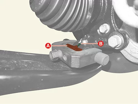
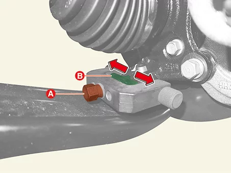
Place the support body (A) between the lower arm and the front axle (B).
Rotate the bolt (A) clockwise, and then insert the support body (B) to broaden the gap.
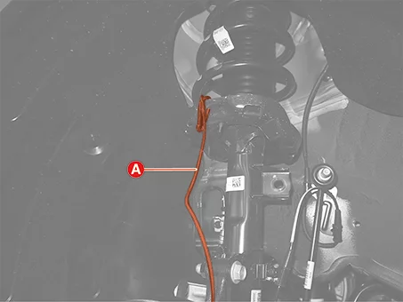
Install the main body (A) between the front strut assembly and front lower arm.
Use the main body (A) of the SST (0K545 - A9100).
Secure the main body with the wire (A) to prevent it from falling.
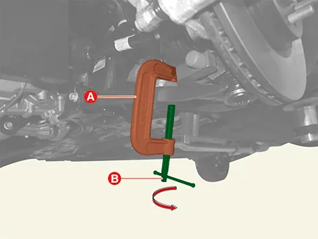
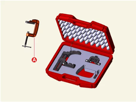
Install the C-clamp (A) by turning the handle (B) to prevent the main body from slipping.
Use the C-clamp (A) of the SST (0K545 - A9100).
Tighten the bolt (A), and then separate the front lower arm from the front axle.
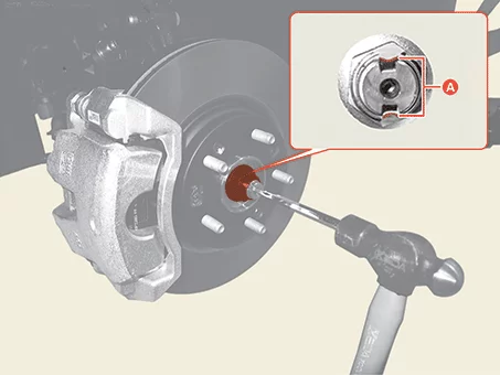
Unlock the driveshaft lock nut caulking (A), by hammering on a chisel or suitable tool.
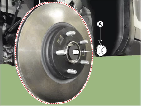
Remove the driveshaft lock nut (A).
Tightening torque : 274.6 - 294 N·m
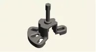
Separate the front driveshaft (A) from the front axle by using the SST (09517 - 4E000).
When removing the driveshaft, do not force pull or over deflect the axle.
Remove the engine room under cover. G 1.6 T-GDI GAMMA II (Refer to Engine Mechanical System - "Engine Room Under Cover") G 2.0 MPI NU (Refer to Engine Mechanical System - "Engine Room Under Cover")
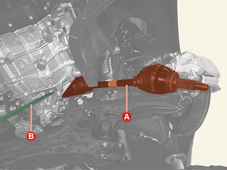
Remove the front driveshaft (A) using a tool such as the pry bar (B). [LH] [RH]
Do not insert the pry bar too deep, as this may damage the oil seal.
Do not pull the driveshaft with excessive force. it may occur the inside of the joint kit is dislocated, and may damage the boot or bearing.
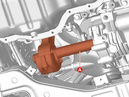
Plug the hole of the transaxle case with the oil seal cap to prevent contamination.
Support the driveshaft properly.
Remove the RH front driveshaft. (Refer to Driveshaft Assembly - "Front Driveshaft")
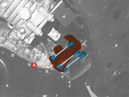
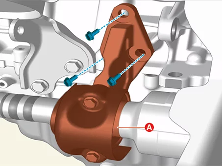
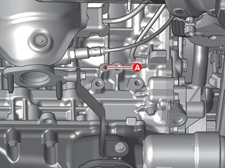
Separate the inner shaft bearing bracket (A) from the cylinder block after removing the bolts.
Tightening torque : 49.0 - 64 N·m
[G 1.6 T-GDI GAMMA II] [G 2.0 MPI NU]
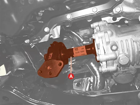
Remove the inner shaft and bearing bracket (A). [G 1.6 T-GDI GAMMA II] [G 2.0 MPI NU]
Inner Shaft and Bearing Bracket
Installation
Install in reverse order of removal.
Do not reuse the driveshaft lock nut.
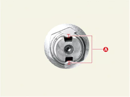
After tightening the driveshaft lock nut, caulk the lock nut to an appropriate depth (A) by using a chisel or suitable tool.
Caulking Depth (A) : 1.5 mm (0.0590 in.) or less
Press the brake pedal to prevent the driveshaft from rotating when tightening the driveshaft lock nut.
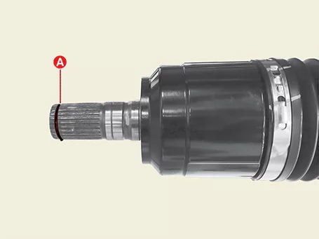
Do not reuse the front drive shaft circlip (A).
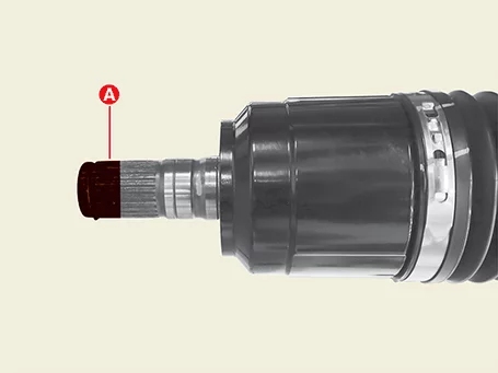
Apply a grease the spline (A) before installing the front driveshaft.
Grease Type : CASMOLY CSG 101 M or equivalent Capacity : 0.5 ~ 1.0 cc
Do not reuse the inner shaft circlip (A).
Apply grease to the spline before installing the inner shaft.
Grease Type : CASMOLY CSG 101 M or equivalent Capacity : 0.5 ~ 1.0 cc
Make sure that the inner shaft bearing bracket is installed at the pin (A) before tightening the bolts.
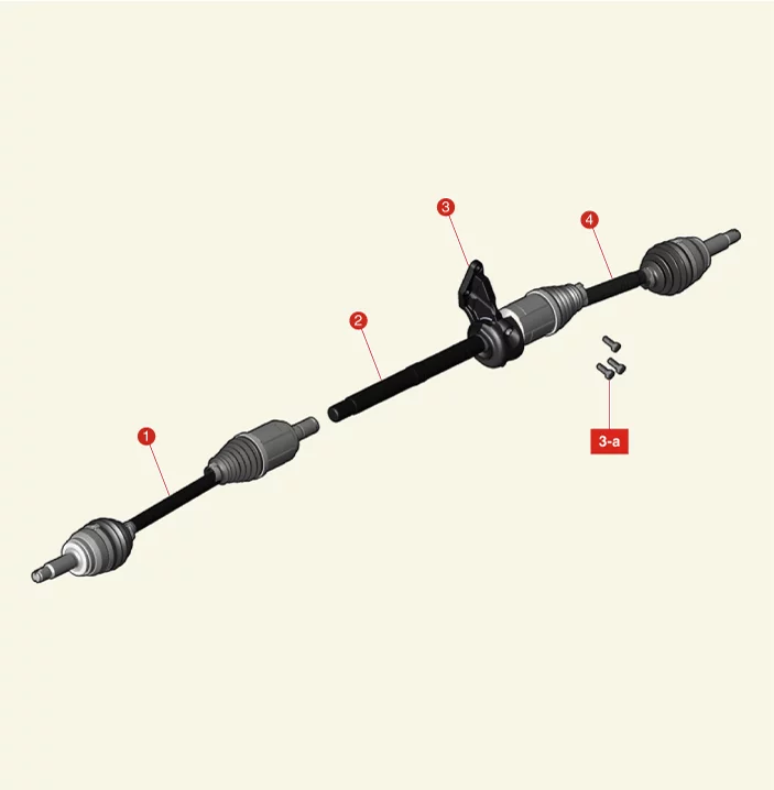
Joint Assembly (Transaxle side) Components and Components Location
Component
LH
1. Wheel Side Joint Housing 2. Circlip (Wheel Side) 3. Large Diameter Boot Band (Wheel Side) 4. Boot (Wheel Side) 5. Small Diameter Boot Band (Wheel Side) 6. Shaft
7. Small Diameter Boot Band (Transaxle Side) 8. Boot (Transaxle Side) 9. Large Diameter Boot Band (Transaxle Side) 10. Spider Assembly 11. Snap Ring 12. Transaxle Side Joint Housing 13. Circlip (Transaxle Side)
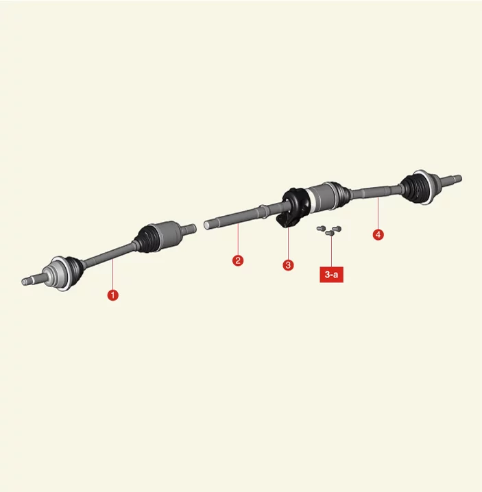
RH - G 1.6 MPI GAMMA, G 1.6 T-GDI GAMMA ll
1. Inner Shaft Assembly 2. Transaxle Side Joint Housing 3. Stopper Ring 4. Spider Assembly Bearing 5. Snap Ring 6. Spider Assembly 7. Large Diameter Boot Band (Transaxle Side) 8. Boot
9. Small Diameter Boot Band (Transaxle Side) 10. Shaft 11. Circlip (Wheel Side) 12. Small Diameter Boot Band (Wheel Side) 13. Boot 14. Large Diameter Boot Band (Wheel Side) 15. Wheel Side Joint Housing
RH - G 2.0 MPI NU
1. Inner Shaft Assembly 2. Transaxle Side Joint Housing 3. Stopper Ring 4. Spider Assembly Bearing 5. Snap Ring 6. Spider Assembly 7. Large Diameter Boot Band (Transaxle Side) 8. Boot
9. Small Diameter Boot Band (Transaxle Side) 10. Shaft 11. Circlip (Wheel Side) 12. Small Diameter Boot Band (Wheel Side) 13. Boot 14. Large Diameter Boot Band (Wheel Side) 15. Wheel Side Joint Housing
Joint Assembly (Transaxle side) Removal
Special Service Tool
Tool Name / Number
Illustration
Description
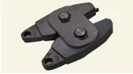
Band installer 0K495 - 2W000
Used for installing hook type boot band (low profile)(Sharing handle with 0K495 - C5000)
Removal
Driveshaft joints require special grease, so do not add any other type of grease.
Do not reuse the boot band.
Remove the front driveshaft. (Refer to Driveshaft Assembly - "Front Driveshaft")
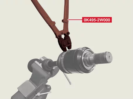
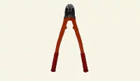
Remove the large diameter boot band using the SST (0K495 - 2W000).
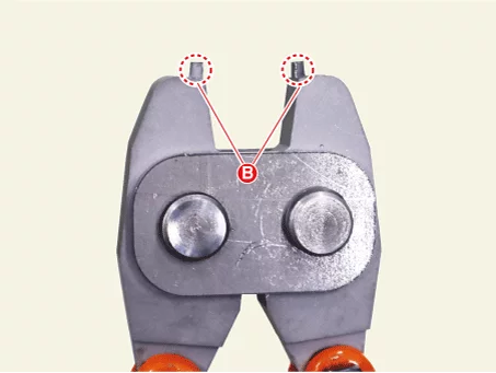
When using the low profile hook type boot band, fit the SST tip (B) into the boot band hole (A) as shown below.
Remove the transaxle side small diameter boot band (A) using the flat-head screwdriver.
Separate the transaxle side joint boot (A) in the direction of the arrow, and then remove the joint stopper ring (B) and joint housing (C).
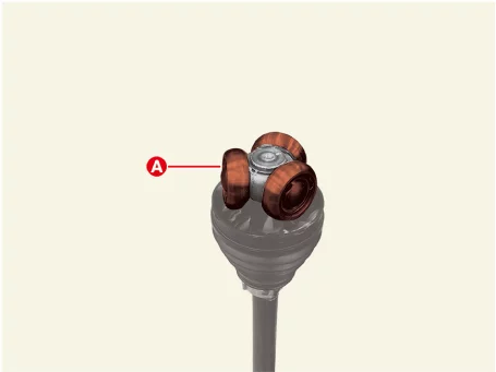
Remove the bearings (A) from the spider assembly.
Remove the snap ring (A) using the snap ring pliers.
Remove the spider assembly (B) from the driveshaft using a puller (A).
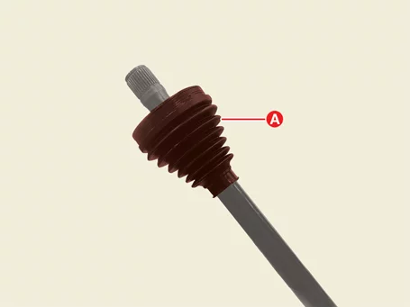
Remove transaxle side boot (A).
Clean the inside of the spider assembly and joint housing.
Remove grease inside the housing as much as possible.
Joint Assembly (Transaxle side) Inspection
Inspection
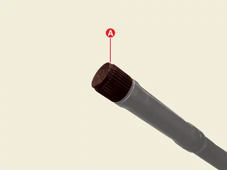
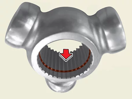
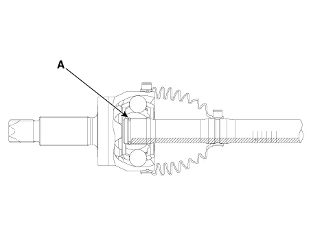
Check spline (A) for damage / wear / crack.
Check the boot for water or foreign objects.
Check joint assembly for damage / wear / crack and rust.
Replace any defective parts.
Joint Assembly (Transaxle side) Installation
Special Service Tool
Tool Name / Number
Illustration
Description
Band installer 0K495 - C5000
Used for installing ear type boot band(Sharing handle with 0K495 - 2W000)
Band installer 0K495 - 2W000
Used for installing hook type boot band (low profile)(Sharing handle with 0K495 - C5000)
Installation
Be careful of dust or foreign substances entering when assembling.
Driveshaft joints require special grease, so do not add any other type of grease.
Do not reuse the boot band.
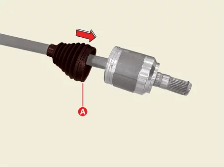
Install the transaxle side boot (A) and boot band (B) on the driveshaft.
Put the boot band (B) first on the driveshaft before installing the boot (A).
Install the spider assembly (A) and snap ring (B) to the driveshaft spline.
When installing the spider assembly (A), install it in the correct direction. If the directionality of the spider assembly is not correct when installation, the snap ring can not be installed.
Use a new joint assembly supplied with the joint kit when replacing the joint assembly.
Do not reuse the snap ring.
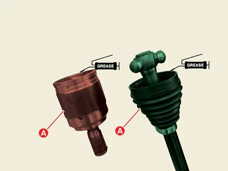
Apply specified grease inside the joint housing (A) and boot (B).
Use the grease provided with the joint/boot kit.
Driveshaft joints require special grease, so do not add any other type of grease.
Apply 20 to 30% grease to the inside of the boot.
Install the bearings (A) to the spider assembly.
Install the transaxle side joint housing (A) and stopper ring (B) to the driveshaft.
Ensure that the stopper ring is installed in the joint housing correctly.
Ensure that the joint housing does not come out when pulled.
Install the boot (A) to the joint housing.
Install the large diameter boot band using the SST (0K495 - 2W000).
Install in the following order: large diameter boot band → small diameter boot band.
Installing in the wrong order can cause leaks.
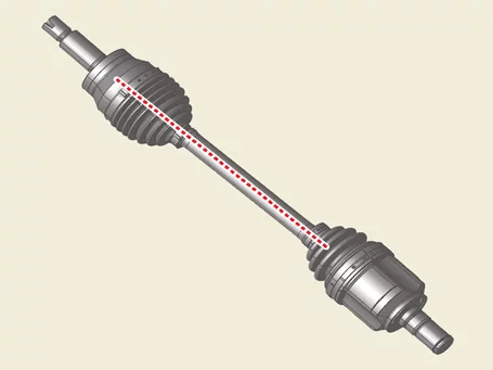
When installing the boot band, align the fastened direction with the wheel side joint boot band.
When using the low profile hook type boot band, fit the SST tip (B) into the boot band hole (A) as shown below.
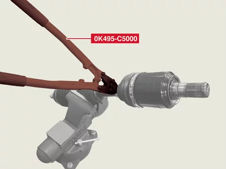
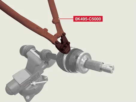
Install the small diameter boot band using the SST (0K495 - C5000).
Install in the following order: large diameter boot band → small diameter boot band.
Installing in the wrong order can cause leaks.
When installing the boot band, align the fastened direction with the wheel side joint boot band.
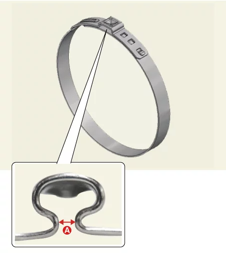
Check the gap (A) of the ear type boot band after installation.
Clearance (A) : 2.0 mm (0.0787 in.) or less
Install the front driveshaft. (Refer to Driveshaft Assembly - "Front Driveshaft")
Joint Assembly (Wheel side) Components and Components Location
Component
LH
1. Wheel Side Joint Housing 2. Circlip (Wheel Side) 3. Large Diameter Boot Band (Wheel Side) 4. Boot (Wheel Side) 5. Small Diameter Boot Band (Wheel Side) 6. Shaft
7. Small Diameter Boot Band (Transaxle Side) 8. Boot (Transaxle Side) 9. Large Diameter Boot Band (Transaxle Side) 10. Spider Assembly 11. Snap Ring 12. Transaxle Side Joint Housing 13. Circlip (Transaxle Side)
RH - G 1.6 MPI GAMMA / G 1.6 T-GDI GAMMA ll
1. Inner Shaft Assembly 2. Transaxle Side Joint Housing 3. Stopper Ring 4. Spider Assembly Bearing 5. Snap Ring 6. Spider Assembly 7. Large Diameter Boot Band (Transaxle Side) 8. Boot
9. Small Diameter Boot Band (Transaxle Side) 10. Shaft 11. Circlip (Wheel Side) 12. Small Diameter Boot Band (Wheel Side) 13. Boot 14. Large Diameter Boot Band (Wheel Side) 15. Wheel Side Joint Housing
RH - G 2.0 MPI NU
1. Inner Shaft Assembly 2. Transaxle Side Joint Housing 3. Stopper Ring 4. Spider Assembly Bearing 5. Snap Ring 6. Spider Assembly 7. Large Diameter Boot Band (Transaxle Side) 8. Boot
9. Small Diameter Boot Band (Transaxle Side) 10. Shaft 11. Circlip (Wheel Side) 12. Small Diameter Boot Band (Wheel Side) 13. Boot 14. Large Diameter Boot Band (Wheel Side) 15. Wheel Side Joint Housing
Joint Assembly (Wheel side) Removal
Special Service Tool
Tool Name / Number
Illustration
Description
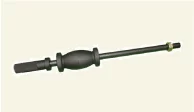
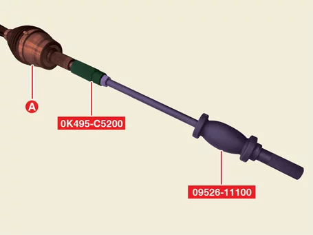
Sliding hammer 09526 - 11100
Used for removal of CV joint (Used with 0K495 - C5200)
Adaptor 0K495 - C5200
Used for removal of CV joint (Used with 09526 - 11100)
Removal
Remove the front driveshaft. (Refer to Driveshaft Assembly - "Front Driveshaft")
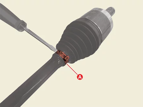
Remove the small diameter boot band (A) using the flat-head screwdriver.
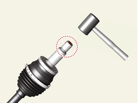
Hammer the joint spline upper side 2 - 3 times with a plastic hammer.
Use a plastic hammer or mallet to prevent damage to the parts.
Release the stuck circlip (A) by hammering it.
Install the SST (0K495 - C5200) on the driveshaft spline (A).
Secure the driveshaft using the vise and remove the joint assembly (A) using SST (09526 - 11100).
Impact the sliding hammer hard to remove the joint assembly at once.
If the joint assembly is not removed at one time, it may not be removed because the circlip is stuck inside. (In this case, replace the driveshaft assembly.)
Remove the large diameter boot band (A) using a flat-head screwdriver or a remover.
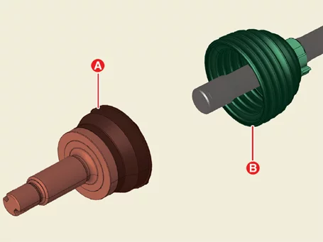
Separate the joint boot (A) and joint assembly (B).
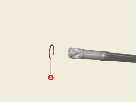
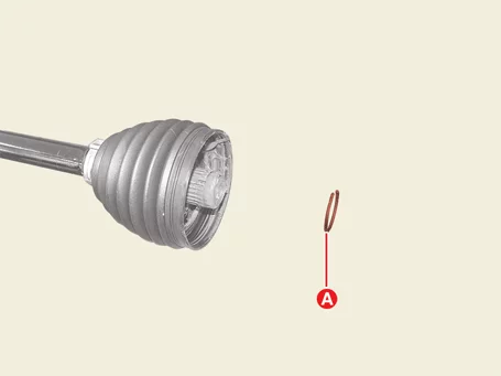
Remove the circlip (A) from the driveshaft.
Joint Assembly (Wheel side) Inspection
Inspection
Check spline (A) for damage / wear / crack.
Check the boot for water or foreign objects.
Check joint assembly for damage / wear / crack and rust.
Replace any defective parts.
Joint Assembly (Wheel side) Installation
Special Service Tool
Tool Name / Number
Illustration
Description
Band installer 0K495 - C5000
Used for installing ear type boot band(Sharing handle with 0K495 - 2W000)
Installation
Be careful of dust or foreign substances entering when assembling.
Driveshaft joints require special grease, so do not add any other type of grease.
Do not reuse the boot band.
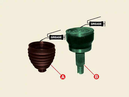
Apply specified grease inside the joint housing (A) and boot (B).
Use the grease provided with the joint/boot kit.
Apply 20 to 30% grease to the inside of the boot.
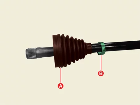
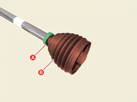
Pre-install the wheel side boot band (A) and boot (B) on the driveshaft.
Pre-install the boot band first before install the wheel side boot.
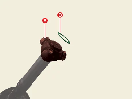
Install the circlip (A) to the driveshaft.
Install the wheel side joint (A) to the boot (B).
Hammer the joint spline upper side 2 - 3 times with a plastic hammer.
Use a plastic hammer or mallet to prevent damage to the parts.
Ensure that the joint assembly and the circlip (A) are installed securely by pulling it.
There should be a feeling of being stuck when pulling and pushing the joint assembly.
Install the large diameter boot band using the SST (0K495 - C5000).
Install in the following order: large diameter boot band → small diameter boot band.
Installing in the wrong order can cause leaks.
When installing the band, align the boot band with the joint boot band.
Check the gap (A) of the ear type boot band after installation.
Clearance (A) : 2.0 mm (0.0787 in.) or less
Install the small diameter boot band using the SST (0K495 - C5000).
Install in the following order: large diameter boot band → small diameter boot band.
Installing in the wrong order can cause leaks.
When installing the band, align the boot band with the joint boot band.
Check the gap (A) of the ear type boot band after installation.
Clearance (A) : 2.0 mm (0.0787 in.) or less
Install the front driveshaft. (Refer to Driveshaft Assembly - "Front Driveshaft")