Electric Vehicle Battery System
On-Board Charger (OBC) Schematic Diagrams
In this manual: Electric Vehicle Battery System
~1min read
Schematic Diagrams
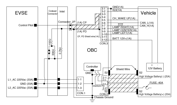
| Terminal | Description | Specification | |
| Current (Normal) | Voltage (Maximum) | ||
| 1 | Phase Voltage (L1)_220 V AC | 33 A | 310 V AC |
| 2 | Ground | ||
| 3 | Phase Voltage (L2)_220 V AC | ||
Output Connector (DC)
| Terminal | Description | Specification | |
| Current (Normal) | Voltage (Maximum) | ||
| 1 | High Voltage Battery (-) | 25 A | 495 V DC |
| 2 | High Voltage Battery (+) | ||
| 3 | High Voltage Interlock Pin | ||
| 4 | High Voltage Interlock Pin | ||
Signal Connector
| Terminal | Description | Specification | |
| Current (Normal) | Voltage (Maximum) | ||
| 1 | Ground | 1 A | 0 V |
| 2 | IG3 | 18 V | |
| 3 | Connection Determination (EVSE) | 5V | |
| 4 | Control Pilot (EVSE) | 12V | |
| 5 | Relay Operation | 18 V | |
| 6 | CAN Low | 1.5-2.5 V | |
| 7 | CAN High | 2.5-3.5 V | |
| 8 | Charge Status Indicator (Right) | 18 V | |
| 9 | Charge Status Indicator (Center) | 18 V | |
| 10 | Charge Status Indicator (Left) | 18 V | |
| 11 | CP, PD Protective Ground | 0 V | |
| 12 | Auxiliary Battery 12 V (+) | 18 V | |
Test yourself
A quick Kia Soul EV Owner's Manual quiz: every answer comes with an explanation and a link to the manual page.
Was this page helpful?