Front Axle Assembly
Components and Component Location
Components

| 1. Front Brake Disc 2. Hub Assembly |
3. Dust cover 4. Front knuckle |
Repair Procedures
Removal
[2WD]
Remove the wheel nuts, front wheel and tire (A) from the front hub.
Tightening torque: 107.9–128 N·m

Remove the front wheel guard.

Remove the front stabilizer bar.
(See Suspension System - Front Stabilizer Bar)
Remove the engine room side cover.
D 2.2 R VGT (See Engine Mechanical System - Under Engine Room Cover)
G 2.0 T-GDI THETA II (See Engine Mechanical System - Engine Room). Under Cover")
G 3.3 T-GDI LAMBDA II (See Engine Mechanical System - Engine Room). Under Cover")
Loosen the lower arm pin (A) and nut (B).
Tightening torque: 88.3–108 N·m

Loosen the compression arm pin (A) and nut (B).
Tightening torque: 88.3–108 N·m

Loosen the compression arm bolt and nut on the subframe.
Tightening torque: 156.9 - 176 N·m

Disconnect the wheel speed sensor connector.

Remove the lower arm using a ball joint remover (A).

Remove the compression arm using a ball joint remover (A).

Remove the brake caliper.
(See Brake System - Front Disc Brake)
Remove the tie rod end nut.
Tightening torque: 88.3–108 N·m

Remove the steering knuckle using a ball joint remover (A).

Loosen the screw and remove the brake disc.
Tightening torque: 4.9–5.9 N·m

Loosen the dust cover bolt, then remove the dust cover.
Tightening torque: 10.8–12.7 N·m N·m


Loosen the hub assembly mounting bolts and remove the hub assembly.
Tightening torque: 88.3–108 N·m

Loosen the wheel speed sensor bracket bolt and remove the wheel speed sensor bracket.
Tightening torque: 6.9–10.8 N·m

Loosen the brake hose bracket bolt from the caliper.
Tightening torque: 6.9–10.8 N·m

Loosen the brake cooling cover mounting bolts.
Tightening torque: 7.8–11.8 N·m
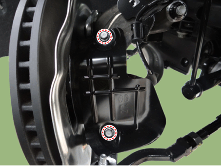
Loosen the steering knuckle upper bolt and nut.
Tightening torque: 78.5–98 N·m

Remove the steering knuckle using SST (0K517-J5100).
Reference value: less than 8.0 mm (0.31 in.)

Install in the reverse order of removal.
Inspect the front wheel alignment.
(See Suspension System - Alignment)
[AWD]
Remove the wheel nuts, front wheel and tire (A) from the front hub.
Tightening torque: 107.9–128 N·m
Remove the brake caliper.
(See Brake System - Front Disc Brake)
Loosen the lower arm pin (A) and nut (B).
Tightening torque: 88.3–108 N·m

Remove the lower arm using a ball joint remover (A).

Loosen the compression arm pin (A) and nut (B).
Tightening torque: 88.3–108 N·m

Remove the compression arm using a ball joint remover (A).

Remove the tie rod end nut.
Tightening torque: 88.3–108 N·m
Remove the steering knuckle using a ball joint remover (A).
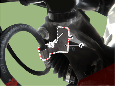
Remove the brake hose bracket (A).
Tightening torque: 6.9–10.8 N·m
Loosen the screw and remove the brake disc.
Tightening torque: 4.9–5.9 N·m

Unstake the drive shaft hub nut lock by tapping a chisel with a hammer.

Loosen the staked nut (A) and separate the hub assembly from the drive shaft.
Tightening torque: 294.2–314 N·m

Loosen the hub assembly bolts (A) and remove the hub assembly.
Tightening torque: 88.3–108 N·m

Loosen the wheel speed sensor mounting bolt (A) and disconnect the wheel speed sensor.
Tightening torque: 6.9–10.8 N·m

Remove the brake cooling shroud (A).
Tightening torque: 7.8–11.8 N·m

Remove the wheel speed sensor bracket (A).
Tightening torque: 6.9–10.8 N·m

Loosen the steering knuckle upper bolt and nut.
Tightening torque: 78.5–98 N·m
Remove the steering knuckle using SST (0K517-J5100).
Reference value: less than 8.0 mm (0.31 in.)
Install in the reverse order of removal.
Inspect the front wheel alignment.
(See Suspension System - Alignment)
Inspection
Check the hub for cracks and worn splines.
Check the brake disc for scratches and damage.
Check the joint for cracks.
Check the bearing for cracks or damage.
Test yourself
A quick Kia Stinger CK quiz: every answer comes with an explanation and a link to the manual page.