Intake Manifold
Components and Component Location
Components

| 1. Intake Manifold 2. VCM Actuator 3. Clip 4. VCM Shaft |
5. Intake Manifold Gasket 6. Intake Manifold Bracket (LH) 7. Intake Manifold Bracket (RH) |
Repair Procedures
Removal and Installation
Disconnect the negative battery cable.
Remove the engine compartment under cover (front).
(See Engine and Transaxle Assembly - Under Hood)
Drain the engine coolant.
(Refer to Cooling System - "Engine Coolant")
Remove the engine cover.
(See Engine and Transaxle Assembly - Engine Cover)
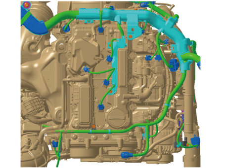
Disconnect the wiring connectors and harness clips, and remove the connector brackets around the intake manifold.


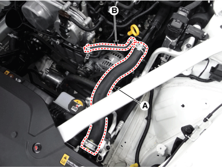
Disconnect the upper radiator hose (A) and water hose (B).
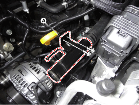
Remove the water outlet pipe assembly (A).
Tightening Torque: 9.8–11.8 N·m
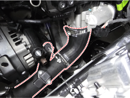
Remove the intercooler outlet hose and pipe assembly (A).
Tightening torque:
Hose clamp:
4.9–6.9 N·m (0.5–0.7 kgf·m, 3.6–5.1 ft-lbf, 43.4–60.8 in-lbf)
(If equipped with a cap, tighten until the cap is removed.)
Bolt:
14,7–19.6 N·m
Disconnect the positive crankcase ventilation (PCV) hose (A).
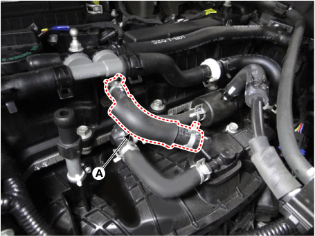
Disconnect the hose (A) from the Purge Control Solenoid Valve (PCSV).

Disconnect the vacuum hose (A).
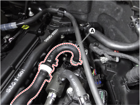
Remove the generator.
(See Engine Electrical System - "Alternator")
Loosen the electronic throttle control (ETC) module mounting bolts.
(Refer to Engine Control/Fuel System - Electronic Throttle Control (ETC) System).
Remove the oil level gauge tube.
(Refer to Lubrication System - Oil Level Gauge and Tube)
Remove the intake manifold support (A).
Tightening torque: 18.6 – 24 N·m

Remove the intake manifold stopper bolt (A).
Tightening torque: 18.6 – 24 N·m
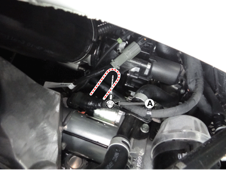
Disconnect the vacuum hose (A).
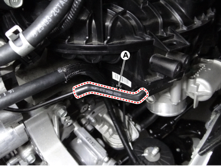
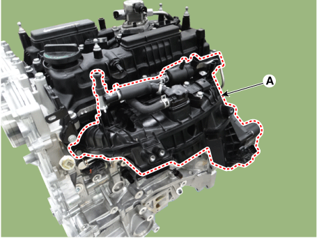
Remove the intake manifold (A).
Tightening torque: 18.6 – 24 N·m
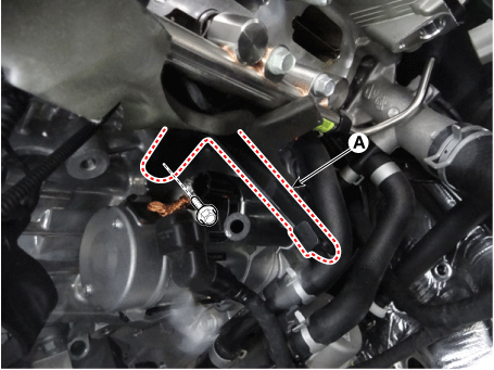
Remove the intake manifold support (A).
Tightening torque: 18.6 – 24 N·m
Install in the reverse order of removal.
Test yourself
A quick Kia Stinger CK quiz: every answer comes with an explanation and a link to the manual page.