Steering Column and Shaft
Components and Component Location
Components

| 1. Steering Column Module (SCM) | 2. Steering Column Module (SCM) Bracket |
Specifications
Specification
| Item | Specifications |
| Rated Voltage | 12 V DC |
| Operating Voltage Range | 9–16 V DC |
| Operating Temperature Range | -30°C to +75°C |
| Storage Temperature Range | -40°C ~ +85°C |
| Dark Flow | Max. 1 mA |
Description and Operation
Description
Stores the optimal steering column position on the tilt and telescopic modules and recalls the steering column position when the position is changed.
Steering column position recall is prohibited while the vehicle is in motion for safety reasons. An emergency stop function is provided that stops the recall and related operations. The following functions are provided.
Manual Operation
You can use the manual switch to adjust the steering column tilt up and down and telescope in and out.
When a signal is received from the manual switch, the IPS is activated to change the steering column position.
Memory Function
You can use the IMS switch to store and recall tilt and telescopic positions for up to 3 drivers.
When the IMS switch is activated, the system receives CAN data from the DDM and recalls the optimal steering column position set by the driver.
When the IMS switch is activated, the system recalls the stored settings based on CAN data from the DDM.
Smart Key Memory/Recall: You can use the smart key to store and recall steering wheel positions for 2 drivers.
Automatic Tilt and Telescopic Position Adjustment: The tilt and telescopic position can be adjusted automatically based on key input/output data (CAN data from BCM).
Circuit Diagrams
Schematic Diagrams

Terminal Function

| Pin No. | Description | Pin No. | Description |
| 1 | B + | 12 | IG1 |
| 2 | Tilt sensor input | 13 | Position sensor output power |
| 3 | Telescopic sensor input | 14 | - |
| 4 | Tilt up switch input | 15 | Tilt down switch input |
| 5 | Telescopic direction switch input | 16 | Telescopic reverse direction switch input |
| 6 | CAN High | 17 | - |
| 7 | CAN Low | 18 | - |
| 8 | - | 19 | Ground |
| 9 | Tilt up motor output | 20 | Ground power |
| 10 | Battery + | 21 | Telescopic motor forward output |
| 11 | Tilt down motor output | 22 | Telescopic motor reverse output |
Repair Procedures
Removal
Steering Column Module (SCM)
Turn the ignition switch OFF and disconnect the negative (-) battery cable.
Remove the airbag lower panel.
(Refer to Body - "Under Cover Panel")
Disconnect the steering column module connector.
[Left-hand drive]
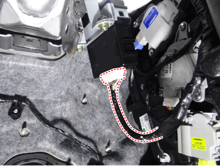
[Right-hand drive]
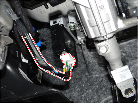
Loosen the steering column module bracket bolts and remove the steering column module.
[Left-hand drive]
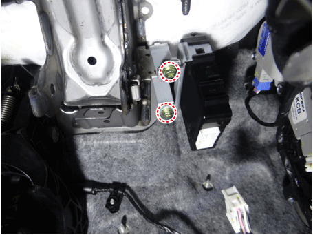
[Right-hand drive]
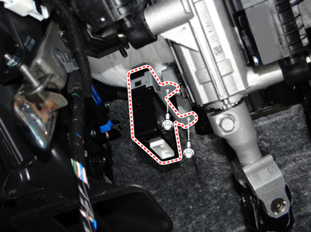
Install in the reverse order of removal.
Steering Column Module (SCM) Switch
Turn the ignition switch OFF and disconnect the negative (-) battery cable.
Remove the airbag lower panel.
(Refer to Body - "Under Cover Panel")
Disconnect the steering column module connector.
(Refer to Body - "Steering Column Shroud Panel")
Disconnect the steering wheel module switch connector and clip.
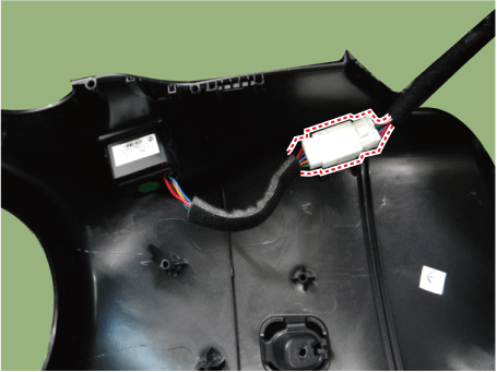
With the driver, remove the steering column module switch.

Install in the reverse order of removal.
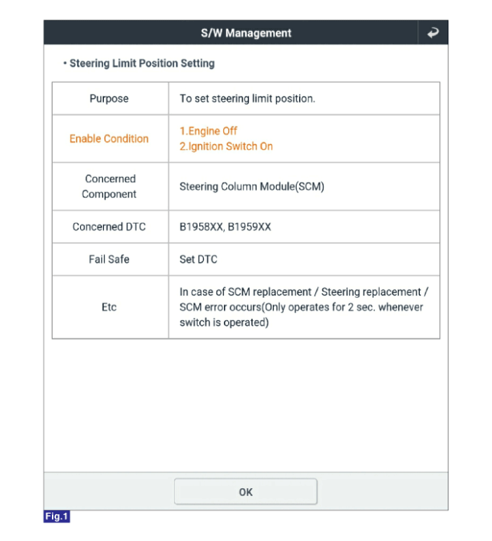
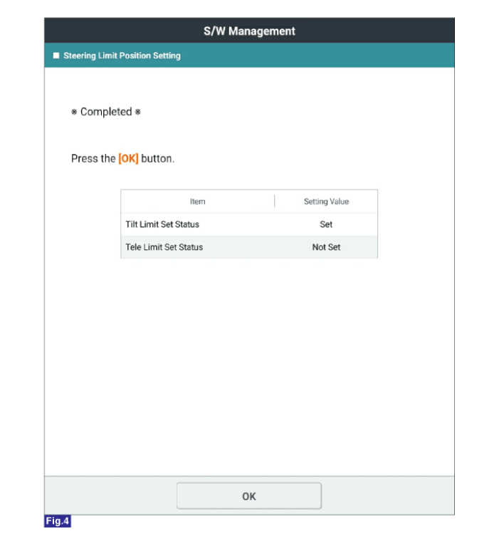
Steering Angle Limit Setting Parameter
Perform the "Steering Angle Limit Setting" using the KDS.


Test yourself
A quick Kia Stinger CK quiz: every answer comes with an explanation and a link to the manual page.