Electric power steering
Description and Operation
Description
The EPS (Electric Power Steering, steering assist system) is an independent steering system that uses an electric motor to assist steering effort.
The EPS control module controls the motor based on input signals from the torque sensor and the steering angle sensor via CAN (Controller Area Network). This provides more precise and timely control of the power steering assist than a conventional hydraulic system.
The EPS components (steering angle sensor, torque sensor, safety relay, etc.) are located inside the steering column. The EPS unit, steering column, and EPS unit cannot be disassembled for inspection. Replace them if necessary.
Diagnosis Note
| Problem Factor | Check Item | Symptom of Malfunction | Description | NOTE |
| Drop, Impact and Overload | Motor | Abnormal Noise | - Visible or invisible damage may occur. The steering wheel may pull to one side if parts are dropped. Precision motor / ECU parts are sensitive to vibration and shock. Overloading may cause unexpected damage. | - Do not use a damaged EPS. - Do not overload any part. |
| ECU | - Circuit damage - Incorrect weld point - Broken printed circuit board - Damaged precision parts |
|||
| Torque Sensor | Insufficient steering effort | Overloading the INPUT shaft may cause torque sensor malfunction. | - Do not strike connecting parts (when inserting and tightening). - Use the specified tool to remove the steering wheel. (Do not hammer it.) - Do not use a damaged EPS. |
|
| Shaft | Insufficient steering wheel effort (uneven between left and right sides) | Do not use a damaged EPS. | ||
| Pull / Dent | Restrain | - Malfunction - Power assist operation not possible - EPS malfunction |
Disconnection between the connector part and the harness | Do not overload the suspension. |
| Abnormal storage temperature | Engine / ECU | Abnormal steering effort due to incorrect engine/ECU operation | - Waterproof under normal conditions - Even a small amount of moisture may cause malfunction of precision motor / ECU parts. |
- Maintain normal storage temperature and humidity. - Avoid immersion in water. |
Do not apply impact to electronic parts. If dropped or struck, replace them with new ones.
Avoid exposing electronic parts to heat and moisture.
Do not touch the connector terminals to avoid deformation and static electricity.
Do not strike the motor and torque sensor parts. If they are dropped or damaged, replace them with new ones.
The connector must be disconnected or connected with the ignition switched off.
Components and Component Location
Components
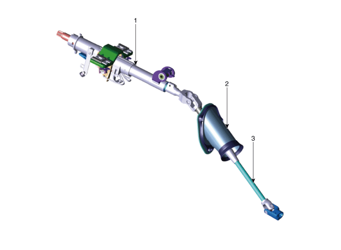
| 1. Steering column 2. Dust cover |
3. Universal joint |
Circuit Diagrams
Schematic Diagrams
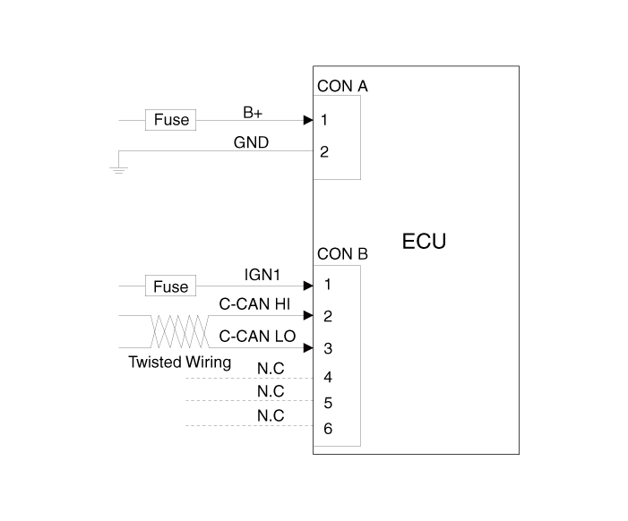
Harness Connector

| Item | Pin | Pin Name |
| MDPS Power | 1 | Battery + |
| 2 | Battery - | |
| MDPS Control Unit | 1 | Ignition |
| 7 | CAN High | |
| 8 | CAN Low |
Repair Procedures
General Inspection
Before and after servicing the EPS system, perform troubleshooting and inspection as follows. Compare the system condition with the normal condition in the table below, and if abnormal symptoms are found, perform the necessary troubleshooting and inspection actions.
| Test Conditions | Normal condition: The motor should not provide steering assist. | ||
| Symptom | Possible Cause | Remedy | |
| Ignition OFF | The motor provides steering assist. | ASP is not calibrated. | Perform ASP calibration using the scan tool. |
| IG Power Supply Circuits | Inspect the IG power supply line. | ||
| Test Conditions | Normal condition: The electric motor does not assist steering, and the warning lamp is illuminated. | ||
| Symptom | Possible Cause | Remedy | |
| IG ON / Engine OFF | The motor provides steering assist. | ASP is not calibrated. | Perform ASP calibration using the scan tool. |
| EMS CAN signal not received. | Inspect the CAN line. | ||
| The warning lamp does not illuminate. | Cluster Malfunction | Inspect the cluster and wiring harness. | |
| Test Conditions | Normal condition: The motor provides steering assist, and the warning lamp does not illuminate. | ||
| Symptom | Possible Cause | Remedy | |
| IG ON / Engine ON | The warning lamp is illuminated and the motor does not provide steering assist. | EPS (Battery Power) and IG Power Supply Malfunction | Inspect the connector and harness for the EPS (battery power) and the IG power supply line. |
| DTC is detected by the system. | Perform a self-diagnosis using a scan tool, and repair or replace as necessary. | ||
| The warning lamp illuminates and the electric motor provides steering assist. | ASP is not calibrated. | Perform ASP calibration using the scan tool. | |
| CAN communication error between EPS and cluster. | Inspect the CAN line. | ||
ASP: Absolute Steering Position
CAN: Controller Area Network
EMS: Engine Management System
Caution for ASP (Absolute Steering Position) Calibration or EPS Type Recognition
Before calibrating the ASP or recognizing the EPS type, make sure the battery is fully charged.
Be careful not to disconnect any cables connected to the vehicle or the scan tool during ASP calibration or EPS type recognition.
After completing ASP calibration or EPS type recognition, switch the ignition off and wait a few seconds. Then start the engine to confirm normal vehicle operation.
ASP Calibration
Select "Steering Angle Sensor (SAS) Calibration".
Continue the test according to the instructions on the screen.


EPS Type Recognition Procedure
Select "EPS Variant Coding".
Continue the test according to the instructions on the screen.


Test yourself
A quick Kia Stinger CK quiz: every answer comes with an explanation and a link to the manual page.