Starter
Specifications
SPECIFICATIONS
▷12 V, 1.2 kW: ISG only
| Position | SPECIFICATIONS | |
| rated voltage | 12 V, 1.2 kW | |
| Number of Gear Teeth | 13 | |
| Performance [No Load, 11.5 V] |
Amplifier | Max. 117 A |
| SPEED | Not less than 3200 rpm | |
▷12 V, 0.9 kW: WITHOUT ISG
| Position | SPECIFICATIONS | |
| rated voltage | 12 V, 0.9 kW | |
| Number of Gear Teeth | 11 | |
| Performance [No Load, 11.5 V] |
Amplifier | Max. 85 A |
| SPEED | Minimum 3300 rpm | |
Components and Components Location
COMPONENTS LOCATION
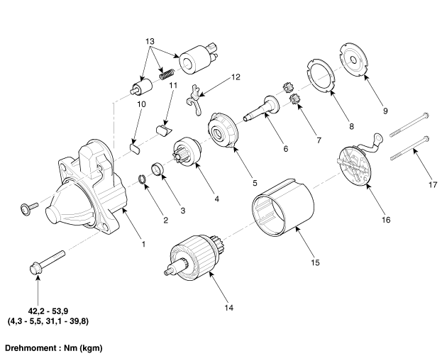
| 1. Front Housing 2. Snap Ring 3. Stopper 4. Overrunning Clutch 5. Ring Gear 6. Planetary Shaft 7. Planetary Gear 8. Gasket 9. Shielding |
10. Lever Plate 11. Lever Boot 12. Lever 13. Magnetic Switch 14. Plunger 15. Yoke 16. Brush Holder 17. Long Bolt |
Description and Operation
Description
The starting system consists of the battery, starter, magneto, ignition and the neutral safety switch (A/T) or clutch pedal switch (M/T), ignition key switch, connecting cables and battery cable.
When the ignition switch is turned to the "START" position, current flows and supplies power to the solenoid coil of the starter motor.
When power is supplied, the plunger and lever are activated, the pinion engages with the ring gear and closes the contacts, and the starter rotates.
To prevent armature damage from excessive speed during cranking, a one-way clutch is installed to prevent the engine from overrunning the starter.
With the ISG function, the starter has to perform considerably more work. Therefore, the starter is designed for a considerably higher number of starting cycles. The starter components are adapted to the higher requirements.

1. Solenoid Switch 2. Brush 3. Armature 4. Overrunning Clutch
Schematic diagrams
Circuit diagram
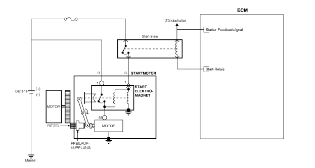
repair procedures
expansion
Turn the ignition switch OFF and disconnect the negative (-) battery terminal.
Remove the air filter.
(Refer to Engine Mechanical - "Air Cleaner").
Remove the battery.
(Refer to Group EE — Battery)
Disconnect the wire from the "B" terminal (A) of the alternator.
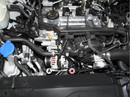
Remove the nut securing the "B" terminal of the starter magnetic switch, then the starter cable (B) and the ST connector (A).
Starter magnetic switch "B" terminal nut: 9.8 ~ 11.8 N·m
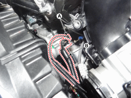
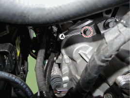
Remove the upper starter mounting bolt (A).
Starter mounting bolt: 42.2 ~ 54 N·m
Raise the vehicle.
| 8th. | Loosen the fasteners, then remove the engine undercover (A). 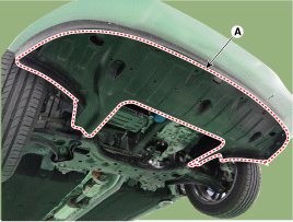 |
Remove the drive belt.
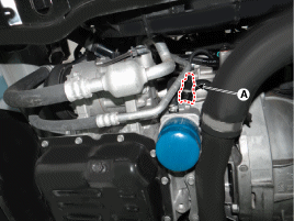
Disconnect the oil pressure switch connector (A).
Disconnect the compressor connector, then loosen the mounting bolts and increase the clearance between the compressor (A) and the engine to make room for the starter.
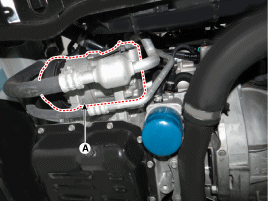
Remove the lower starter mounting bolt (A).
Starter mounting bolt: 42.2 ~ 54 N·m

Installation
Installation is the reverse of removal.
Assembly
Installation is performed in the reverse order of removal.
TEST
INSPECT AND TEST ARMATURE
Remove the starter motor.
Disassemble the starter as described earlier in this section.
Inspect the armature for wear or damage caused by contact with the permanent magnet. If the armature is worn or damaged, replace the armature.
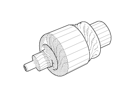
Inspect the commutator surface. If the surface is dirty or burnt, resurface it on a lathe according to the following specifications.
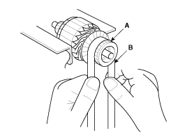
Inspect the commutator outer diameter. If the diameter is below the specification, replace the armature.
Commutator diameter
Standard value (new part): 33.0 mm
Wear limit: 32.4 mm
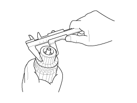
Measure the commutator runout (A).
If the commutator runout is within specification, check the commutator for carbon deposits or copper particles between the segments.
If the commutator runout exceeds the limit, replace the armature.
Commutator runout
Standard value (new part): 0.02 mm max.
Wear limit: 0.05 mm
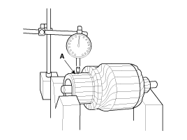
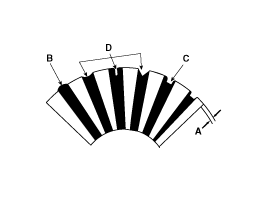
Measure the undercut depth (A) between the segments. If there is no undercut (B) but the mica protrudes, cut the insulation with a suitable saw to the specified depth. Remove all debris (C) from the cuts. The cuts must be neither too wide nor too narrow, and must not be V-shaped (D).
Commutator undercut depth
Standard value (new part): 0.5 mm
Limit: 0.2 mm
| 8th. | Check the continuity between the commutator segments. If any segments are open, replace the armature. 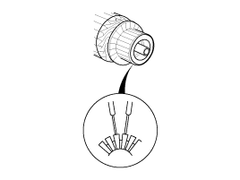 |
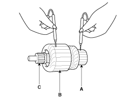
Using an ohmmeter, check that there is no continuity between the commutator (A) and the armature coil (B). Also check that there is no continuity between the commutator (A) and the armature shaft (C). If continuity exists, replace the armature.
INSPECT STARTER BRUSH
Worn or oil-soaked brushes must be replaced.

INSPECT STARTER BRUSH HOLDER
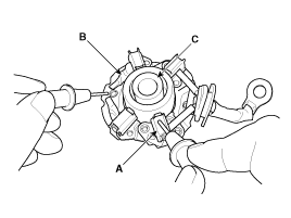
Make sure there is no continuity between the brush holder (A) and the (+) plate (B). If there is continuity, replace the brush holder.
INSPECT OVERRUNNING CLUTCH
Slide the overrunning clutch along the shaft.
Replace if the part does not slide smoothly.
Rotate the overrunning clutch in both directions.
Make sure it locks in one direction and rotates smoothly in the other. If it locks in neither or both directions, replace the overrunning clutch.

If the starter pinion is worn or damaged, the overrunning clutch must be replaced. (The pinion is not sold separately.)
If the pinion is damaged, check the condition of the flywheel or torque converter drive plate ring gear.
CLEANING
Do not immerse parts in solvent.
If the stator and/or armature are immersed in cleaning solution, the insulation will be damaged. Wipe these components with a cloth only.
Do not immerse the drive in cleaning solution.
The overrunning clutch is lubricated at the factory; cleaning solution would wash the lubricant out of the overrunning clutch.
Clean the drive with a brush moistened with cleaning solution, then dry it with a cloth.
Test yourself
A quick Kia Stonic quiz: every answer comes with an explanation and a link to the manual page.