Engine Control System/Fuel System
Spezialwerkzeuge
SPECIAL SERVICE TOOLS
| Tool Name / Number | Illustration | Beschreibung |
| Fuel pressure gauge 09353-24100 |
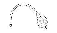 |
Zur Druckmessung in der Kraftstoffleitung |
| Adapter, fuel pressure gauge 09353-24100 |
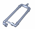 |
Zum Anschluss zwischen Hochdruck-Kraftstoffpumpe und Niederdruck-Kraftstoffzufuhrleitung Zum Messen des Drucks in der Kraftstoffleitung |
| Steckschlüssel für die beheizte Lambdasonde 09392-1Y100 |
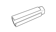 |
Zum Aus-/Einbau der beheizten Lambdasonde ※SST 09392-2H100 kann ebenso verwendet werden |
| Torque wrench socket 09314-3Q100 or 09314-27130 (19 mm) |
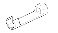 |
Verwendet für Aus-/Einbau der Hochdruck-Kraftstoffleitung |
| Injektor-Dichtringführung und Kalibrierwerkzeug 09353-2B000 |
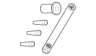 |
Zum Einbau der Dichtung am Einspritzventil |
Malfunction
GRUNDSÄTZLICHE FEHLERSUCHE
BASIC TROUBLESHOOTING FLOW
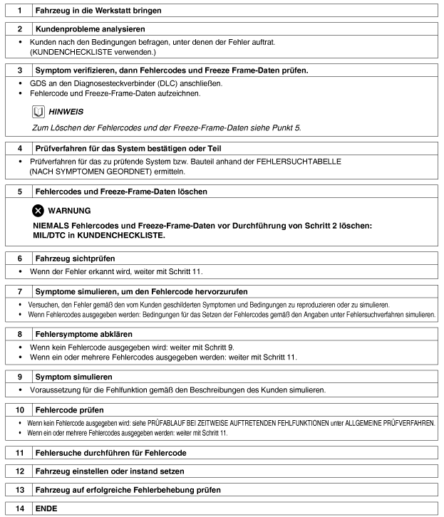
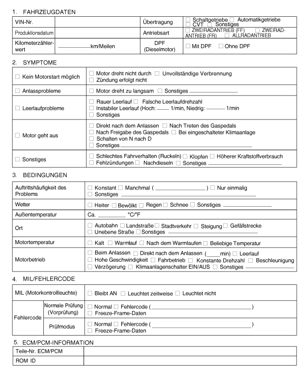
CHECKLIST
ALLGEMEINE PRÜFVERFAHREN
CONDITIONS FOR ELECTRONIC COMPONENT RESISTANCE MEASUREMENT
Bei heißem Motor (direkt nach der Fahrt) kann der gemessene Widerstandswert vom Sollwert abweichen. Widerstände müssen daher, soweit nicht anders vermerkt, bei Umgebungstemperatur (20 °C)
PRÜFABLAUF BEI ZEITWEISE AUFTRETENDEN FEHLFUNKTIONEN
Troubleshooting is especially difficult when a malfunction has occurred only once and cannot be easily reproduced. For example, a fault that occurs only when the vehicle is cold but not when it has reached operating temperature. In this case, the "Customer Checklist" should be filled out very carefully so that all conditions under which the malfunction occurred can be simulated.
Fehlercode(s) löschen.
Check connectors. Check connectors for poor connection, pull on wire harness, check for deformed, broken or corroded terminals. Make sure all connectors are fully locked and secured.
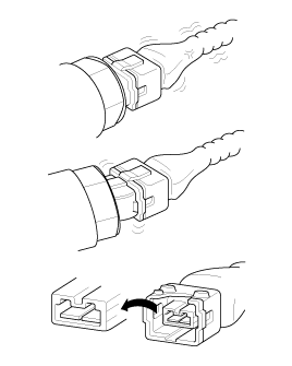
Stecker und Kabelstränge leicht auf und ab als auch nach links und rechts bewegen und schütteln.
Fehlerhaftes Bauteil instand setzen oder austauschen.
Im Rahmen einer Probefahrt sicherstellen, dass die Fehlfunktion nicht Mehr Auftritt.
● VIBRATION SIMULATION
| a. | Sensoren und Stellglieder : Sensoren, Stellglieder oder Relais mit den Fingern antippen, um Vibrationen zu simulieren. |
| b. | Connector and Harness : Stecker und Kabelbaum vorsichtig auf und ab und dann hin und her schütteln. |
● HITZE SIMULIEREN
| a. | Eventuell fehlerhafte Bauteile mit einem Fön oder einer vergleichbaren Wärmequelle erwärmen. |
● RAIN SIMULATION
| a. | Spray the vehicle with water to simulate rain or high humidity. |
● ELEKTRISCHE LAST SIMULIEREN
| a. | Alle elektrischen Verbraucher (Radio, Gebläse, Licht, Heckscheibenheizung, usw.) einschalten, um eine Extreme Elektrische Last zu simulieren. |
INSPECTION OF CONNECTORS
Handling of Connectors
a. Beim Trennen von Steckerverbindungen niemals am Kabelstrang ziehen.
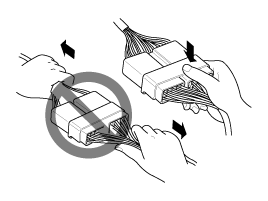
b. Zum Abziehen verriegelter Stecker erst die Verriegelung durch Drücke oder Zurückziehen lösen.
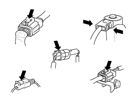
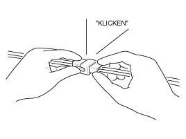
b. When connecting connectors, listen for the click sound. This indicates the connector is securely locked.
d. Messgeräte-Prüfspitzen immer von der Kabelstrangseite her an die zu prüfende Klemme anlegen.
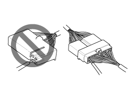
e. Klemmen wasserdichter Kabelstecker von der Klemenseite her prüfen. Sie sind von der Kabelstrangseite nicht erreichbar.
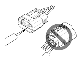
Püfpunkte für Stecker
a. Bei angelklemmtem Stecker:
Stecker halten und Verbindung als auch Verriegelung der Stecker prüfen.
b. Bei abgeklemmtem Stecker:
Stecker auf fehlende, verformte oder beschädigte Klemmen prüfen. Dazu leicht am Kabelstrang ziehen.
Klemmen auf Oxidation, Verschmutzung und Verformungen sichtprüfen.
b. Festen Sitz der Steckerklemmen prüfen:
Insert the new terminal (replacement part/type: plug) into a terminal connector (type: receptacle) and check that the connector is securely seated.
d. Gently pull on the wires to check that they are firmly seated in the terminals.
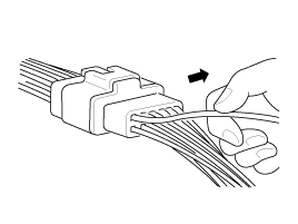
Reparieren der Steckverbinderklemme
a. Klemmen mit Druckluft und/oder Putzlappen reinigen.
b. Wenn die Kraft zum Anklemmen ungewöhnlich ist, Steckerklemme (Bauart: Buchse) ersetzen.
HARNESS INSPECTION
Vor dem Ausbau eines Kabelstrangs dessen Verlegung und Befestigung untersuchen, damit er ordnungsgmeäß wieder eingebaut werden kann.
Auf verdrehte, herausgezogene oder lockere Kabelstränge prüfen.
Kabelstrang auf ungewöhnlich hohe Temperatur prüfen.
Check whether the harness contacts sharp edges or is subject to vibration.
Anschluss zwischen Kabelstrang und zugehörigem Bauteil prüfen.
If the insulation is damaged, carefully repair or replace the harness.
STROMKREISPRÜFUNG
● AUF STROMKREISUNTERBRECHUNG PRÜFEN
Stromkreis auf Unterbrechung prüfen
Durchgangsprüfung
CIRCUIT INSPECTION
An open circuit (See Fig. 1) can be identified using Inspection Step 2 (Continuity Check) or Inspection Step 3 (Voltage Check).
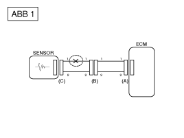
Durchgangsprüfung
Specification (Resistance)
1 Ω or less → Circuit is normal
1 MΩ or more → Open circuit
a. Disconnect connectors (A) and (C), then measure the wire resistance between connectors (A) and (C) as shown in [FIG. 2].
In [FIG. 2], the measured resistance is higher than 1 MΩ for wire 1 and lower than 1 Ω for wire 2. Therefore, the open circuit is in wire 1 (wire 2 is normal). To locate the exact open point, inspect each section of wire 1 as described in the next inspection step.
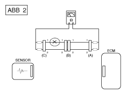
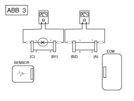
b. Disconnect connector (B) and measure the resistance between connector (C) and (B1), and between (B2) and (A), as shown in [FIG. 3].
In this case, the resistance measured between connector (C) and (B1) is higher than 1 MΩ, so the open circuit is between terminal 1 of connector (C) and terminal 1 of connector (B1).
Spannungsprüfung
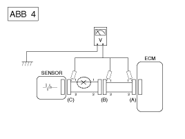
a. With the connectors connected, measure the voltage between body ground and terminal 1 of each connector (A), (B) and (C), as shown in [FIG. 1].
In the example, the measured voltages are 5 V, 5 V and 0 V. Therefore, the open circuit is between connectors (C) and (B).
● AUF KURZSCHLUSS PRÜFEN
Prüfverfahren für Kurzschluss an Masse
Durchgangsprüfung mit Karosseriemasse
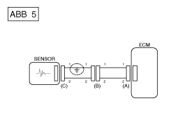
Bei einem Kurzschluss an Masse (Siehe ABB. 5) kann der Fehler mit Hilfe des Prüfschritts 2 (Durchgangsprüfung mit Karosseriemasse) lokalisiert werden.
Continuity Check (to Body Ground)
Specification (Resistance)
1 Ω oder geringer → Stromkreis an Masse kurzgeschlossen
1 MΩ or more → Circuit is normal
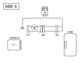
a. Disconnect connectors (A) and (C), then measure the resistance between connector (A) and body ground as shown in [FIG. 6].
The measured resistance is less than 1 Ω for wire 1 and more than 1 MΩ for wire 2. The short to ground is in wire 1 (wire 2 is normal). To locate the exact short point, inspect each section of wire 1 as described in the next inspection step.
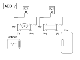
b. Disconnect connector (B). Measure the resistance between connector (A) and body ground, and between connector (B1) and body ground (See Fig. 7).
The resistance measured between connector (B1) and body ground is 1 Ω or less. The circuit between terminal 1 of connector (C) and terminal 1 of connector (B1) is shorted to ground.
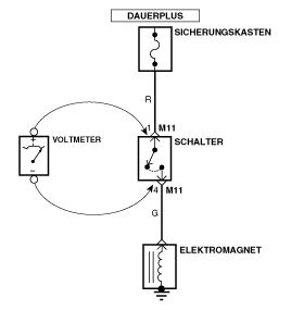
● Test for Spannungsabfall
Anhand dieses Tests wird überprüft, ob die Spannung entlang eines Kabels abfällt oder über einen Anschluss oder über einen Schalter.
| A. | Connect the positive lead of the voltmeter to the wire end (or connector or switch side) closest to the battery. |
| B. | Connect the negative lead to the other wire end. (or the other side of the connector or switch) |
| C. | Den Stromkreis schließen. |
| D. | The voltmeter shows the voltage difference between two points. A difference or drop of more than 0.1 V (50 mV in 5 V circuits) may indicate a malfunction. Check the circuit for loose or corroded terminals. |
POSSIBLE CAUSES OF SYMPTOM
| SYMPTOM | INSPECTION PROCEDURE | AUCH PRÜFEN |
| Engine Does Not Start (Engine does not crank) |
|
|
| Engine Does Not Start (Incomplete combustion) |
|
|
| Anlassprobleme |
|
|
| Rough Idle (Rough, uneven or incorrect idle speed) |
|
|
| Engine Misfire |
|
|
| Poor Driveability (Hesitation) |
|
|
| Knocking |
|
|
| Hoher Kraftstoffverbrauch |
|
|
| Fuel Overflow When Refueling (Fuel overflows during refueling) |
|
|
Test yourself
A quick Kia Stonic quiz: every answer comes with an explanation and a link to the manual page.