Charging System
Bauteile und bauteile-Übersicht
BAUTEILE-ÜBERSICHT
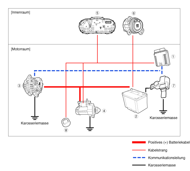
● ECM
- Battery
③ Generator
④ Starter
● Instrument Panel Fuse Block
⑥ Ignition Switch or Engine Start Button
⑦ Battery sensor
* Hood Switch
Beschreibung und bedienung
Beschreibung
Das Ladesystem besteht aus einer Batterie, einer Lichtmaschine mit eingebautem Regler und der Ladekontrollleuchte mit Leitungen.
The alternator contains eight integrated diodes that convert alternating current (AC) to direct current (DC).
Dadurch liefert die Klemme "B" der Lichtmaschine Gleichstrom.
The charging voltage of this alternator is controlled by the battery voltage sensing system. The main components of the alternator are the rotor, stator, rectifier, brushes, bearings and pulley. The brush holder contains an integrated electronic voltage regulator.
Generator Control System
Das Generator-Managementsystem regelt den Einstellpunkt der Ladespannung zur Verringerung des Kraftstoffverbrauchs, verwaltet die Generatorlast unter verschiedenen Betriebsbedingungen, erhält die Batterieladung und schützt die Batterie vor Überladen. Das ECM regelt die Spannungserzeugung über das Tastverhältnis (Laderegelung, Entladeregelung, normale Regelung), basierend auf dem Batteriezustand und den Betriebsbedingungen des Fahrzeugs.
The system performs discharge control when the vehicle accelerates. The alternator load is reduced and the vehicle uses electrical power from the battery.
The system performs charge control when the vehicle decelerates. The alternator output is increased and the battery is charged.
Schematische darstellungen
Schematic Diagram
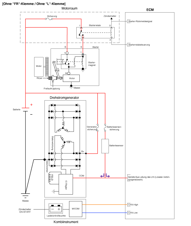
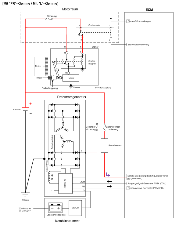
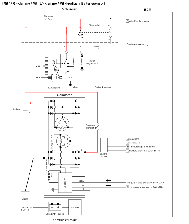
Repair Procedures
INSPECTION
Inspection Points
Überprüfung der Batterieeffizienz
Überprüfung der Batteriespannung
Überprüfung der Ladespannung
GENERAL INSPECTION
Überprüfung der Klemme auf festen Sitz
Überprüfung des Masseanschlusses von Motor/Getriebe
Überprüfung Massestatus des Kabelbaums
Überprüfung der elektrischen Spezifikationen
Kontrolle des Kriechstroms
Überprüfung der Batteriekapazität
Überprüfung der Batterieeffizienz
Überprüfung der Batteriespannung
Nach einer Fahrt mit dem Fahrzeug und wenn seit Abstellen des Motors Weniger als 20 Minuten vergangen sind, die Zündung einschalten und Verbraucher (Scheinwerfer, Gebläse und heizbare Heckscheibe usw.) für 60 Sekunden einschalten, damit die Ladungsspitzen entfernt werden.
Zündung und alle Verbraucher ausschalten.
Measure the voltage between the battery terminals (+ and -).
Standard range: approx. 12.5 - 12.9 V [at 20 °C]
Wenn die Batteriespannung zu niedrig ist, Batterie aufladen.
GENERAL INSPECTION
Überprüfen, dass die Batterieklemmen nicht loss oder korrodiert sind.
(Refer to Charging System - "Battery")
Sicherungen auf Durchgang prüfen.
Alternators
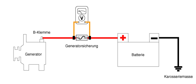
Generatorsicherung (A) auf Durchgang prüfen.
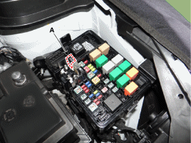

Die Spannung wie in der folgenden Abbildung gezeigt messen.
Standard value: 0 V
If the alternator fuse is blown, replace it as follows:
a. Zündung ausschalten und Minuskabel (-) der Batterie abklemmen.
b. Befestigungsmuttern (A) das Batteriepluspols (+) entfernen.
b. Replace the normal alternator fuse or the battery cable.
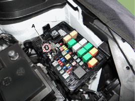
d. Installation is performed in the reverse order of removal.
Antriebsriemen überprüfen.
Antriebsriemen auf fortgeschrittenen Verschleiß und Ausfransungen sichtprüfen.
Wenn Mängel feststellbar sind, Antriebsriemen ersetzen.
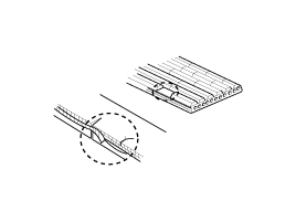
Antriebsriemenspannung messen und einstellen.
(Refer to Engine Mechanical - "Drive Belt")
Visually inspect the alternator wiring and check for abnormal noise.
Prüfen, ob der Kabelstrang in ordnungsgemäßem Zustand ist.
Bei laufendem Motor prüfen, ob die Lichtmaschine ungewöhnliche Geräusche verursacht.
Stromkreis der Ladekontrollleuchte prüfen.
Warm up the engine and then stop it.
Alle Verbraucher ausschalten.
Turn the ignition switch ON. Check that the charging warning light illuminates.
Start the engine. Check that the light turns off.
Wenn die Leuchte nicht wie angegeben erlischt, muss eine Fehlersuche am Ladekontrollleuchtenstromkreis durchgeführt werden.
Überprüfung der Klemme auf festen Sitz
Überprüfung der Bauteilposition
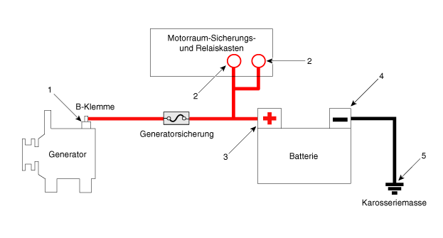
| 1. Alternator B+ Terminal 2. Positive (+) Terminal of Engine Compartment Fuse and Relay Box 3. Battery Positive (+) Terminal |
4. Battery Negative (-) Terminal 5. Body Ground |
Inspection of Engine/Transaxle Ground Status
Inspection of Ground Condition of Wiring Harness

| 1. Engine Ground (Engine ↔ Chassis) 2. Transaxle Ground (Transaxle ↔ Chassis) |
Check the specified electrical values (voltmeter and ammeter readings)
SPANNUNGSABFALLPRÜFUNG DER AUSGANGSLEITUNG DER LICHTMASCHINE
Bei dieser Prüfung wird anhand des Spannungsabfallverfahrens ermittelt, ob die Verkabelung zwischen den Klemme "B" der Lichtmaschine und der Positiven (+) Batterieklemme in Ordnung ist.
Vorbereitung
a. Zündung ausschalten.
b. Disconnect the output wire from the alternator 'B' terminal. Connect the ammeter: connect the test probe (+) to the alternator 'B' terminal and the test probe (-) to the output wire connector disconnected previously. Connect the voltmeter: connect the test probe (+) to the alternator 'B' terminal and the test probe (-) to the battery positive (+) terminal.
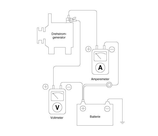
INSPECTION
a. Engine Analysis
b. Scheinwerfer und Gebläse einschalten, Motordrehzahl anheben, bis das Amperemeter 20A anzeigt. Spannung am Voltmeter zu diesem Zeitpunktablesen.
RESULT
a. Die Voltmeteranzeige sollte der Vorgabe entsprechen.
Standard Value: Max. 0.2 V
b. If the voltmeter reading is over 0.2 V, it can be assumed that the wiring is faulty. In this case, check the wiring between the alternator "B" terminal and the battery positive terminal. Check the cable for loose connections and discoloration indicating overheating of the cable. Repair any faults before repeating the test.
b. To continue the test, run the engine at idle. Turn off the headlights and blower motor, and stop the engine.
LICHTMASCHINEN-AUSANGSSTROMSTÄRKE PRÜFEN
Mit diesem Test wird festgestellt, ob die Lichtmaschinen-Ausgangsstromstärke der nominellen Stromstärke entspricht.
Vorbereitung
a. Before the test, check the following items and correct if necessary:
Check the vehicle battery for good condition. For battery inspection, refer to the "Battery" section.
Die Batterie, die zum Prüfen des Ausgangsstroms verwendet wird, sollte teilweise enladen sein.
The test cannot be performed correctly with a fully charged battery, as the load is insufficient.
Die Spannung des Generatorantriebsriemens überprüfen. Zum Prüfen der Riemenspannung siehe den Abschnitt "Riemenspannung prüfen".
b. Zündung ausschalten.
b. Battery
d. Disconnect the alternator output wire from the alternator "B" terminal.
e. Connect a DC ammeter (0 to 150 A) in series between the alternator 'B' terminal and the disconnected output wire connector. Make sure the ammeter negative lead is connected to the disconnected output wire.
f. Connect a voltmeter (0 to 20 V) between the alternator 'B' terminal and ground. Connect the voltmeter positive lead to the alternator 'B' terminal and the voltmeter negative lead to a good ground.
g. Battery
h. Motorhaube geöffnet lassen.
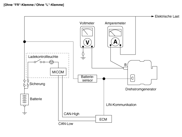
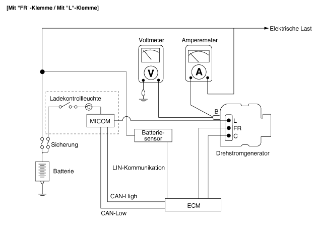
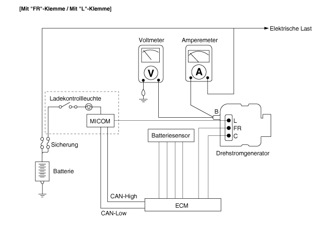
INSPECTION
a. Check that the voltage shown on the voltmeter matches the battery voltage. If the voltmeter shows 0 V, it must be assumed that there is an open circuit or a poor ground in the wire between the alternator "B" terminal and the battery negative (-) terminal.
b. Motor anlassen und Scheinwerfer einschalten.
b. Set the headlights to high beam and the heater blower switch to HIGH. Quickly increase the engine speed to 2500 rpm, then read the maximum output current shown on the ammeter.
RESULT
a. The ammeter reading must be above the limit value. If it is below, although the alternator output wire is in good condition, remove the alternator from the vehicle and inspect it.
Limit value: 60% of rated output
b. After checking the output current, reduce the engine speed to idle, then turn off the ignition.
b. Klemmen sie den Negativpol (-) der Batterie ab.
d. Disconnect the ammeter, voltmeter and tachometer.
e. Connect the alternator output wire and the alternator "B" terminal.
f. Minuspol (-) der Batterie anschließen.
PRÜFUNG DER SPANNUNGSREGELUNG
Mit dieser Prüfung wird festgestellt, ob der elektronische Spannungsregler die Spannung ordnungsgemäß regelt.
Vorbereitung
a. Before the test, check the following items and correct if necessary.
Check the vehicle battery for full charge. For battery inspection, refer to the "Battery" section.
Die Spannung des Generator-Antriebsriemens überprüfen. Zum Prüfen der Riemenspannung siehe den Abschnitt "Riemenspannung prüfen".
b. Zündung ausschalten.
b. Klemmen sie den Negativpol (-) der Batterie ab.
d. Connect a digital voltmeter between the alternator 'B' terminal and ground. Connect the voltmeter positive lead to the alternator 'B' terminal and the voltmeter negative lead to the body ground or the battery negative terminal.
e. Disconnect the alternator output wire from the alternator "B" terminal.
f. Connect a DC ammeter (0 ~ 150 A) in series between the "B" terminal and the disconnected output cable. Connect the negative (-) lead to the other end of the disconnected output cable.
g. Minuspol (-) der Batterie anschließen.
INSPECTION
a. Zündung einschalten und prüfen, ob das Voltmeter folgenden Wert anzeigt.
Standard: Battery Voltage
Wenn das Voltmeter 0 V anzeigt, liegt eine Kabelunterbrechung zwischen Lichtmaschinenklemme "B" und Batterieminuspol vor.
b. Engine Analysis. Turn off all electrical loads.
b. Set the engine speed to approx. 2,500 rpm and read the voltmeter when the alternator output current drops to 10 A or less.
RESULT
a. If the reading differs from the standard value, the voltage regulator or alternator is defective.
Regulation range: 11.7 ~ 15.3 V
b. If the reading differs from the standard value, the voltage regulator or alternator is defective.
b. Klemmen sie den Negativpol (-) der Batterie ab.
d. Disconnect the voltmeter and ammeter.
e. Connect the alternator output wire and the alternator "B" terminal.
f. Minuspol (-) der Batterie anschließen.
Überprüfung der elektrischen Spezifikationen (Verwendung des Voltmeters und des Klemmen-Amperemeters)
SPANNUNGSABFALLPRÜFUNG DER AUSGANGSLEITUNG DER LICHTMASCHINE
Bei dieser Prüfung wird anhand des Spannungsabfallverfahrens ermittelt, ob die Verkabelung zwischen den Klemme "B" der Lichtmaschine und der Positiven (+) Batterieklemme in Ordnung ist.
Vorbereitung
a. Zündung ausschalten.
b. Connect a clamp-type ammeter between the positive (+) battery terminal and the alternator "B" terminal.
b. Connect the positive (+) lead of the voltmeter to the alternator "B" terminal and the negative (-) lead of the voltmeter to the positive battery terminal.
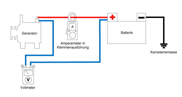
INSPECTION
a. Engine Analysis
b. Turn on the headlights and blower motor. Adjust the engine speed until the ammeter shows 20 A, then read the voltmeter.
RESULT
a. Die Voltmeteranzeige sollte der Vorgabe entsprechen.
Standard Value: Max. 0.2 V
b. If the voltmeter shows a higher value than expected (up to 0.2 V), a poor connection is suspected. In this case, check the wiring between the alternator "B" terminal and the battery positive terminal. Check for loose connections, discoloration due to overheating in the wiring harness, etc. Correct these problems before retesting.
b. After completing the test, run the engine at idle. Turn off the headlights, blower motor and ignition.
LICHTMASCHINEN-AUSANGSSTROMSTÄRKE PRÜFEN
Mit diesem Test wird festgestellt, ob die Lichtmaschinen-Ausgangsstromstärke der nominellen Stromstärke entspricht.
Vorbereitung
a. Before the test, check the following items and correct if necessary:
Check the vehicle battery for good condition. For battery inspection, refer to the "Battery" section.
Die Batterie, die zum Prüfen des Ausgangsstroms verwendet wird, sollte teilweise enladen sein.
The test cannot be performed correctly with a fully charged battery, as the load is insufficient.
Die Spannung des Generatorantriebsriemens überprüfen. Zum Prüfen der Riemenspannung siehe den Abschnitt "Riemenspannung prüfen".
b. Zündung ausschalten.
b. Klemmen sie den Negativpol (-) der Batterie ab.
d. Connect a clamp-type ammeter between the positive (+) battery terminal and the alternator "B" terminal.
e. Connect a DC ammeter (0 to 150 A) in series between the alternator 'B' terminal and the disconnected output wire connector. Make sure the ammeter negative lead is connected to the disconnected output wire.
f. Connect a voltmeter (0 to 20 V) between the alternator 'B' terminal and ground. Connect the voltmeter positive lead to the alternator 'B' terminal and the voltmeter negative lead to a good ground.
g. Minuspol (-) der Batterie anschließen.
h. Motorhaube geöffnet lassen.
INSPECTION
a. Check that the voltage shown on the voltmeter matches the battery voltage. If the voltmeter shows 0 V, it must be assumed that there is an open circuit or a poor ground in the wire between the alternator "B" terminal and the battery negative (-) terminal.
b. Motor anlassen und Scheinwerfer einschalten.
b. Set the headlights to high beam and the heater blower switch to HIGH. Quickly increase the engine speed to 2500 rpm, then read the maximum output current on the ammeter.
RESULT
a. The ammeter reading must be above the limit value. If it is below, although the alternator output wire is in good condition, remove the alternator from the vehicle and inspect it.
Limit value: 60% of rated output
b. After checking the output current, reduce the engine speed to idle, then turn off the ignition.
b. Klemmen sie den Negativpol (-) der Batterie ab.
d. Disconnect the ammeter, voltmeter and tachometer.
e. Connect the alternator output wire and the alternator "B" terminal.
f. Minuspol (-) der Batterie anschließen.
PRÜFUNG DER SPANNUNGSREGELUNG
Mit dieser Prüfung wird festgestellt, ob der elektronische Spannungsregler die Spannung ordnungsgemäß regelt.
Vorbereitung
a. Before the test, check the following items and correct if necessary.
Check the vehicle battery for full charge. For battery inspection, refer to the "Battery" section.
Die Spannung des Generator-Antriebsriemens überprüfen. Zum Prüfen der Riemenspannung siehe den Abschnitt "Riemenspannung prüfen".
b. Zündung ausschalten.
b. Klemmen sie den Negativpol (-) der Batterie ab.
d. Connect a digital voltmeter between the alternator 'B' terminal and ground. Connect the voltmeter positive lead to the alternator 'B' terminal and the voltmeter negative lead to the body ground or the battery negative terminal.
e. Disconnect the alternator output wire from the alternator "B" terminal.
f. Connect a DC ammeter (0 to 150 A) in series between the alternator 'B' terminal and the disconnected alternator cable. Connect the ammeter positive lead to the alternator 'B' terminal and the ammeter negative lead to the cable connector of the alternator output cable disconnected previously.
g. Minuspol (-) der Batterie anschließen.
INSPECTION
a. Zündung einschalten und prüfen, ob das Voltmeter folgenden Wert anzeigt.
Standard: Battery Voltage
Wenn das Voltmeter 0 V anzeigt, liegt eine Kabelunterbrechung zwischen Lichtmaschinenklemme "B" und Batterieminuspol vor.
b. Engine analysis. Turn off all lights and electrical loads.
b. Set the engine speed to approx. 2,500 rpm and read the voltmeter when the alternator output current drops to 10 A or less.
RESULT
a. If the reading differs from the standard value, the voltage regulator or alternator is defective.
Regulation range: 11.7 ~ 15.3 V
b. If the reading differs from the standard value, the voltage regulator or alternator is defective.
b. Battery
d. Disconnect the voltmeter and ammeter.
e. Connect the alternator output wire and the alternator "B" terminal.
f. Minuspol (-) der Batterie anschließen.
Kontrolle des Kriechstroms
[Ammeter Connected in Series]
Alle elektrischen Verbraucher ausschalten, dann Zündung ausschalten.
Alle Türen außer der Motorhaube schließen und dann alle Türen verriegeln.
Steckverbinder des Motorhaubenschalters abziehen.
Open the luggage compartment cover.
Türen schließen oder Türschalter ausbauen.
Einige Minuten warten, bis die elektrischen Systeme des Fahrzeugs in den Ruhemodus wechseln.
Connect the ammeter in series between the battery terminal (-) and the ground cable. Then carefully disconnect the cable from the battery negative post (-).

Den aktuellen Wert des Amperemetersablesen.
Wenn der Kriechstrom den Grenzwert überschreitet, den Stromkreis auf Störungen prüfen. Dazu eine Sicherung nach der anderen entfernen und gleichzeitig den Kriechstrom prüfen.
Nur die Sicherung des Stromkreises, in dem der Kriechstrom vermutet wird, wieder anschließen. Dann eine mit dem Stromkreis verbundene Komponente nach der anderen abklemmen, bis der Kriechstrom unter den Grenzwert fällt.
Limit (after 10 - 20 min.): Up to 50 mA
[Ammeter Connected Using Clamp Type]
Alle elektrischen Verbraucher ausschalten, dann Zündung ausschalten.
Alle Türen außer der Motorhaube schließen und dann alle Türen verriegeln.
Steckverbinder des Motorhaubenschalters abziehen.
Open the luggage compartment cover.
Türen schließen oder Türschalter ausbauen.
Einige Minuten warten, bis die elektrischen Systeme des Fahrzeugs in den Ruhemodus wechseln.
Das Amperemeter in Klemmenausführung am Batterieminuspol (-) anbringen.
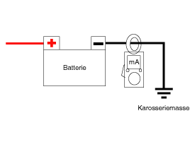
Den aktuellen Wert des Amperemetersablesen.
Wenn der Kriechstrom den Grenzwert überschreitet, den Stromkreis auf Störungen prüfen. Dazu eine Sicherung nach der anderen entfernen und gleichzeitig den Kriechstrom prüfen.
Nur die Sicherung des Stromkreises, in dem der Kriechstrom vermutet wird, wieder anschließen. Dann eine mit dem Stromkreis verbundene Komponente nach der anderen abklemmen, bis der Kriechstrom unter den Grenzwert fällt.
Limit (after 10 - 20 min.): Up to 50 mA
Malfunction
Malfunction
| Symptom | Possible Cause | Measure |
| Ladekontrollleuchte erlischt bei eingeschalter Zündung einschalten abgestelltem Motor nicht, |
Sicherung durchgebrant | SICHERUNGEN PRÜFEN |
| Leuchte ist durchgebrant | Blown fuse | |
| Broken wire harness | Lose Verbindung wieder herstellen | |
| Elektronischer Spannungsregler | Wenn das Licht ausgeht, den Spannungsregler ersetzen. | |
| Ladekontrollleuchte erlischt bei laufendem Motor ausschalten. (Batterie muss häufig wieder aufgeladen werden) |
Drive belt loose or worn | Riemenspannung einstellen oder Riemen ersetzen |
| Battery cable loose, corroded or worn | Kabelanschluss überprüfen, Kabel reparieren oder ersetzen | |
| Electronic voltage regulator or alternator | Wenn das Licht ausgeht, den Spannungsregler oder Generator ersetzen. | |
| WIRING | Verkabelung reparieren oder ersetzen | |
| Charging | Elektronischer Spannungsregler | Wenn das Licht ausgeht, den Spannungsregler ersetzen. |
| Voltage sensing cable | Verkabelung reparieren oder ersetzen | |
| FUSE | Drive belt loose or worn | Riemenspannung einstellen oder Riemen ersetzen |
| Broken wire harness or short circuit | Kabelanschluss überprüfen, Kabel reparieren oder ersetzen | |
| Electronic voltage regulator or alternator | Wenn das Licht ausgeht, den Spannungsregler oder Generator ersetzen. | |
| Schlechte Masseverbindung | Masseanschluss überprüfen oder reparieren. | |
| Charged battery | Battery |
Test yourself
A quick Kia Stonic quiz: every answer comes with an explanation and a link to the manual page.