Heater and Air Conditioner Control Module (Manual)
Components and Components Location
COMPONENTS LOCATION
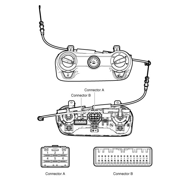
CONNECTOR PIN ASSIGNMENT
| No. | CONNECTOR A | PLUG B |
| 1 | Low | BATTERY |
| 2 | Together | ISG battery |
| 3 | Dimensions | Illumination Lamps (-) |
| 4 | Fan level "medium/low" | Sensor (+5V) |
| 5 | Fan level "medium/high" | ⁻ |
| 6 | High | Intake Actuator Feedback |
| 7 | Evaporator Sensor (+) | |
| 8th | Ambient Temperature Sensor (+) | |
| 9 | ⁻ | |
| 10 | ⁻ | |
| 11 | Intake Actuator (Fresh Air) | |
| 12 | Intake Actuator (Recirculation) | |
| 13 | HTD | |
| 14 | REAR HEATER B/W | |
| 15 | Fan Relay On Signal | |
| 16 | Illumination Lamps (-) | |
| 17 | IGN2 | |
| 18 | IGN1 | |
| 19 | ⁻ | |
| 20 | Max. Fan Relay On Signal | |
| 21 | PTC Relay 3 | |
| 22 | PTC Relay 2 | |
| 23 | PTC On Signal | |
| 24 | Lock Off (+) | |
| 25 | ⁻ | |
| 26 | Chassis CAN [High] | |
| 27 | Chassis CAN [Low] | |
| 28 | ⁻ | |
| 29 | ECV (-) | |
| 30 | ECV (-) | |
| 31 | ground sensor | |
| 32 | Dimensions |
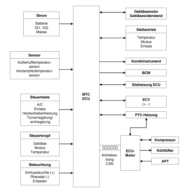
Schematic diagrams
CIRCUIT DIAGRAM
repair procedures
REMOVAL AND INSTALLATION
Disconnect the battery ground cable.
Remove the lower instrument panel trim.
(Refer to Body - "Lower Instrument Panel Trim")
Remove the passenger side instrument panel trim.
(Refer to Body - "Instrument Panel Garnish [Right]")
Remove the glove box.
(Refer to Body - "Glove Box Housing")
Remove the screw and driver-side footwell air duct (A). Do not pull off.
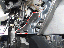
Disconnect the mode control cable (A).
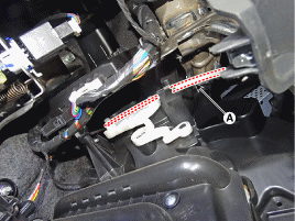
Remove the screw and the passenger side footwell ventilation duct (A).
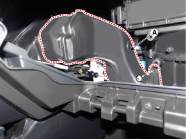
| 8th. | Disconnect the temperature control wire (A). 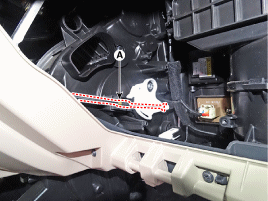 |
Loosen the mounting screws, then remove the heater and air conditioner control unit (A).
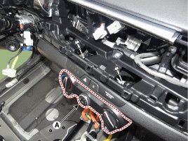
Disconnect the connector (A) from the heater and air conditioner control unit.
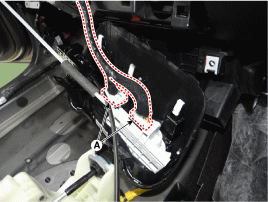
Installation is the reverse of removal.
Test yourself
A quick Kia Stonic quiz: every answer comes with an explanation and a link to the manual page.