Check the battery voltage. (The low beam will turn on when the battery voltage is above 9 V.)
Check the fuse and relay.
Check the ballast polarity. (If the polarity is reversed, the low beam does not illuminate.)
Securely check the bulb connector.
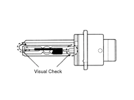
Visually inspect the bulb (without filament): check for damage to the glass, and damage to the upper and lower parts of the glass tube.
After (1) through (5), replace the ballast and igniter (ballast assembly).
Service Procedure and Warning (HID)
No.
Item
Service Procedures
Warning
Notes
1
Bulb Assembly Replacement
Disconnect the power connector from the bulb.
Remove and replace the bulb assembly.
Connect the power connector.
Disconnect the headlamp power connector to avoid voltage.
Other procedures are the same as for halogen bulbs.
2
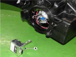
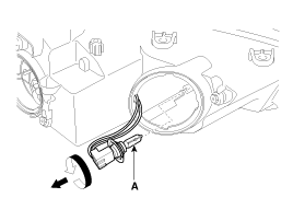
Bulb Replacement
Disconnect the power connector from the lamp. (Headlamp, turn signal lamp, headlamp leveling device)
Remove the bulb assembly.
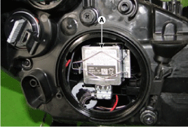
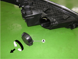
Remove the ballast and dust cover.
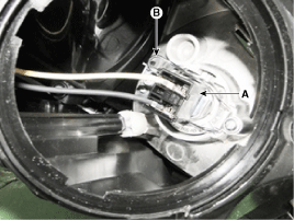
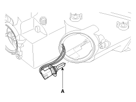
Remove the bulb socket and replace the bulb.
Installation is the reverse of removal.
Disconnect the headlamp power connector to avoid voltage.
Be careful not to damage the bulb, and use only genuine bulbs.
Do not apply excessive force, and install it correctly.
3
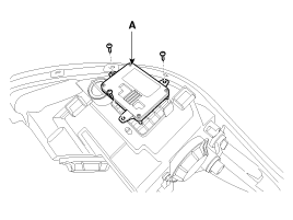
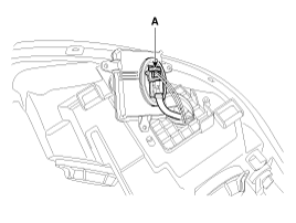
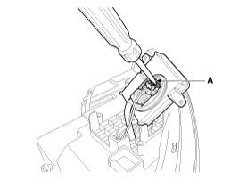
Ballast Replacement (with Built-in Igniter)
Disconnect the power connector from the bulb.
Remove the bulb, then the ballast and dust cover.
Remove the headlamp leveling device, then disconnect the bulb connector.
Connect the bulb socket to the replacement ballast and install the leveling device.
Installation is the reverse of removal.
Disconnect the headlamp power connector to avoid voltage.
Replace only the ballast and install the used bulb.
Replace the auxiliary unit, except the ballast.
4
Other
The power source must match the rated capacity.
Use a fuse and wire of the rated capacity.
The bulb socket must be free of moisture and dirt.
Do not subject the ballast to strong impact, water, or extreme
All parts must be serviced only at designated service centers.
Do not install the HID bulb in other vehicles (dangerous, may cause fire).
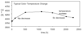
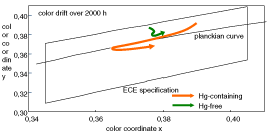
Understanding color change when replacing the HID bulb.
Cause of HID color change. (Color change is a characteristic of HID)
The color change occurs by mixing three elements in the HID bulb.
Color coordinates over bulb life
Chemical compounds in the arc tube:
Xenon gas (inert gas, protects the arc tube)
Mercury (increases voltage, protects arc tube, blue during first 3 seconds)
Metal halide
Sodium (yellow): 0.12 mg
Scandium (blue): 0.06 mg
Iodine (halogen): 0.02 mg
Color change over lighting time
A minimum of 4 seconds is required for stabilization. At first you may see blue for 3 seconds because of mercury.
After stabilization, the color changes due to metal halide.
0 hours: yellow (Na greater than Sc).
10 hours: bright blue (Na and Sc ratio is equal).
Over 1000 hours: blue (Sc greater than Na).
End of service life: when the HID has used up sodium and scandium, the light beam will suddenly dim. You may see red, purple, and flickering on and off.
Vibration resistant, since there is no filament.
The HID bulb has a longer service life than the halogen bulb.
Does not operate if polarity is reversed.
Operating input voltage: 9-16 V
Light ON
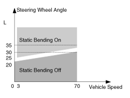
Speed = 3~70 km/h
Steering wheel angle = 30°~35°
Lamp OFF
Speed = 71 km/h or more, 3 km/h or less
Steering wheel angle = 20°~30°
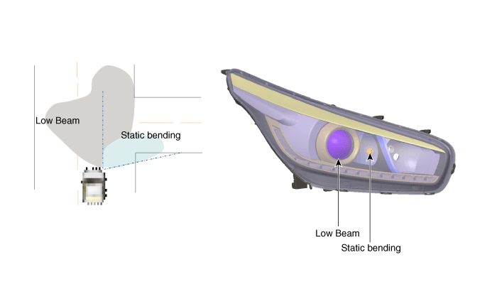
Left/Right turn: Static lamp ON
Description: Static Bending Lamp. When the driver turns the steering wheel, the static bending lamp turns on to provide better night visibility. The static bending lamp turns on depending on vehicle speed and steering wheel angle. The static bending lamp turns on depending on vehicle speed and steering wheel angle. When the driver turns the steering wheel, the static bending lamp turns on to provide better night visibility.
Removal
Disconnect the negative (-) battery terminal.
Remove the front bumper cover. (Refer to Body - "Front Bumper Cover")
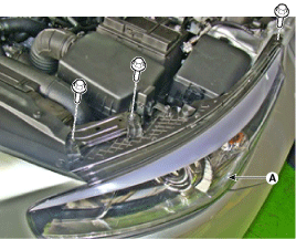
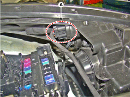
Loosen the headlamp mounting bolts (3 pcs.) and disconnect the headlamp connector (B). Then remove the headlamp assembly (A).
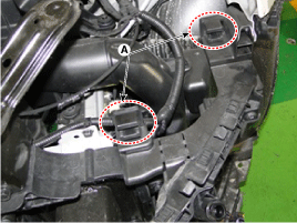
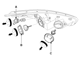
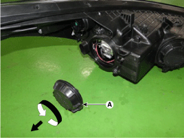
Remove the headlamp dust covers from the headlamp assembly by turning them counterclockwise. A: Turn signal lamp B: Headlamp cap (low) C: Headlamp cover (high)
Installation
Install the headlamp bulbs.
Connect the connectors.
Install the headlamp using the headlamp mounting bolts (3EA).
Connect the negative (-) battery terminal.
Headlamp Aiming Instructions
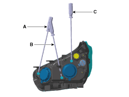
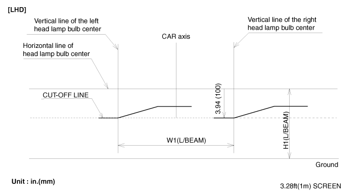
Headlamps must be aimed using proper beam aiming equipment and in accordance with the equipment manufacturer's instructions.Alternately turn the adjusting mechanism to adjust the headlamp direction. If beam aiming equipment is not available, perform the following procedure:
Inflate the tires to the specified pressure and remove any loads from the vehicle except the driver, spare tire and tools.
The vehicle must be on a level floor.
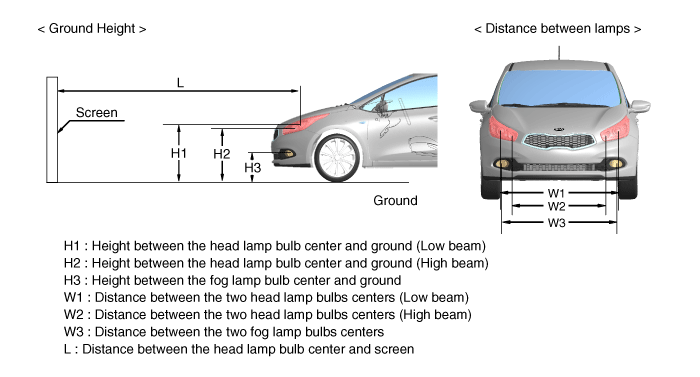
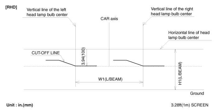
Draw vertical lines (vertical lines passing through the centers of the respective lamps) and a horizontal line (horizontal line passing through the center of the headlamps) on the screen.
With the headlamp and battery in normal condition, aim the headlamps so that the brightest part falls on the horizontal and vertical lines. A: Vertical (high) B: Vertical (low) C: Horizontal (low)
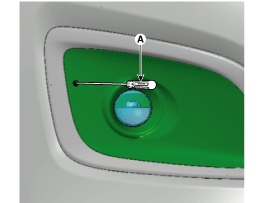
5-door type [Fog][Fog lamp + DRL]
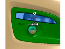
3-door type
Engine type: 1.6 Turbo GDI gasoline
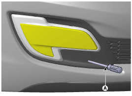
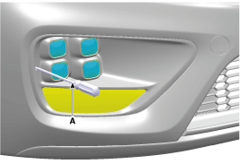
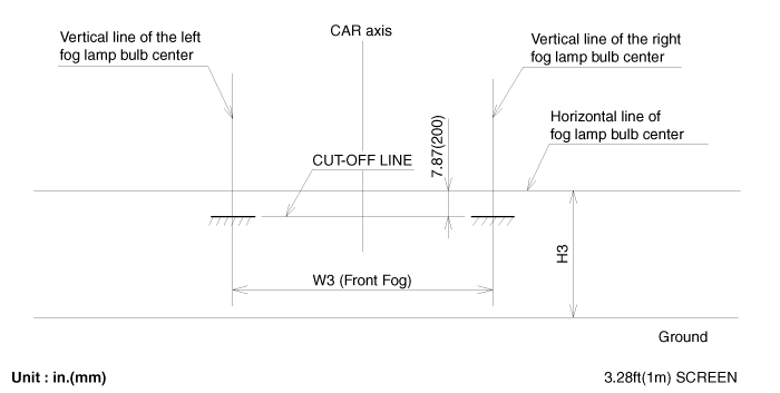
Front Fog Lamp Aiming. Front fog lamps must be aimed in the same way as the headlamps. In normal condition of the front fog lamps and battery, aim the front fog lamps by turning the adjusting screw (A) with a screwdriver. Aiming point of headlamps and fog lamps