Instrument Cluster
Components and Component Location
Components

| 1. Instrument Cluster (General Type) | 2. Instrument Cluster (Control Type) |
Circuit Diagrams
Connector and Terminal Function
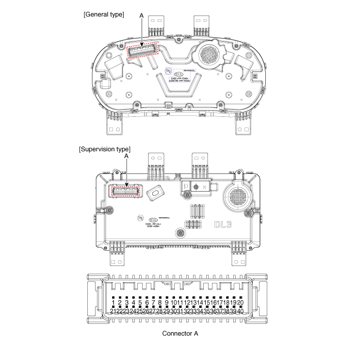

| Pin | Function | Pin | Function |
| 1 | Signal 3 Ground | 21 | Cut-off Switch Input (-) |
| 2 | Illumination (-) | 22 | Cut-off Switch 1 (+) Input |
| 3 | Dimmer Switch Input (Down) | 23 | Cut-off Switch 2 (+) Input |
| 4 | Dimmer Switch Input (Up) | 24 | Drive Mode Switch (CW)_Input |
| 5 | - | 25 | Drive Mode Switch (CCW)_Input |
| 6 | AT ("P" Position) | 26 | - |
| 7 | AT ("R" Position) | 27 | - |
| 8 | AT ("N" Position) | 28 | Active ECO Switch_Input |
| 9 | AT ("D" Position) | 29 | MM-CAN (Low) |
| 10 | AT ("S" Position) | 30 | MM-CAN (High) |
| 11 | - | 31 | Engine Running Status_Output |
| 12 | Vehicle speed output | 32 | C-CAN (High) |
| 13 | Generator Input | 33 | C-CAN (Low) |
| 14 | Fuel Sender (+) Input | 34 | Manual Automatic Lever (+)_Input |
| 15 | - | 35 | Manual Automatic Lever (-)_Input |
| 16 | Fuel sender input (-) | 36 | - |
| 17 | - | 37 | Ground (Signal 1) |
| 18 | General Type: Airbag Input (+) / Control Type: - | 38 | - |
| 19 | Oil Pressure Switch Input | 39 | IGN1 |
| 20 | - | 40 | Battery (+) |
Repair Procedures
Removal
Disconnect the negative battery cable.
Remove the cluster fascia.
(Refer to Body — "Instrument Panel")
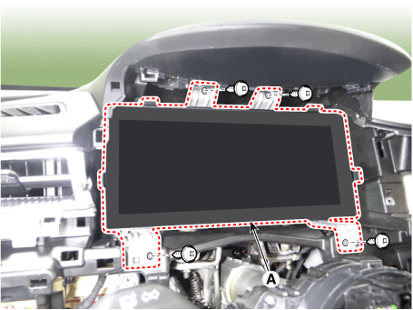
Remove the instrument cluster (A) by loosening the mounting screws.
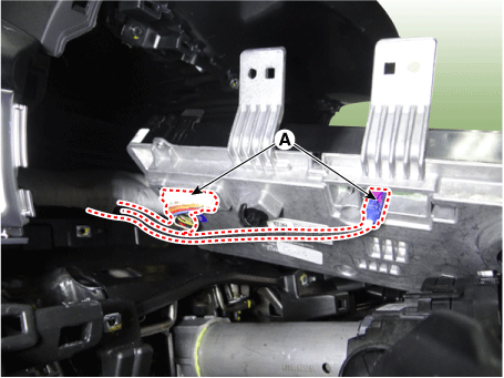
Disconnect the instrument cluster connectors (A).
Installation
Install in the reverse order of removal.
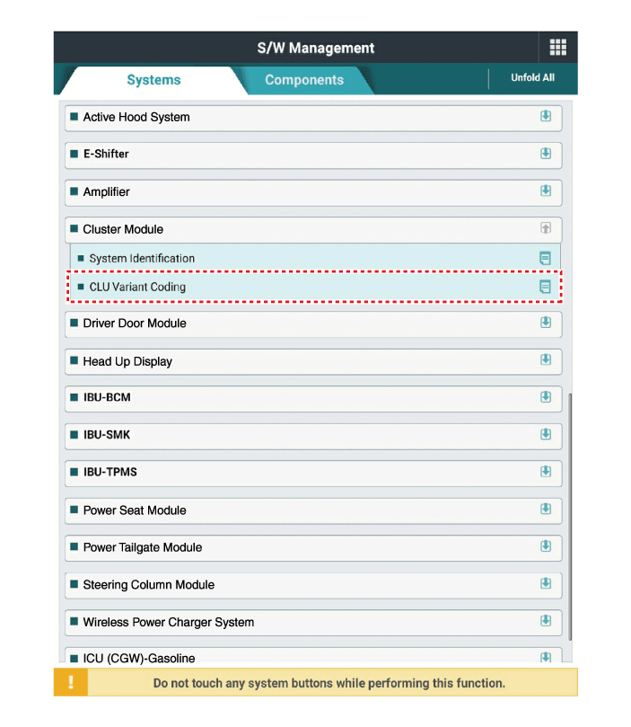
After replacing the cluster with a new one, the "Variant Coding" procedure must be performed.
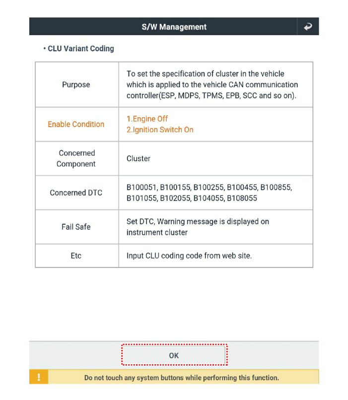
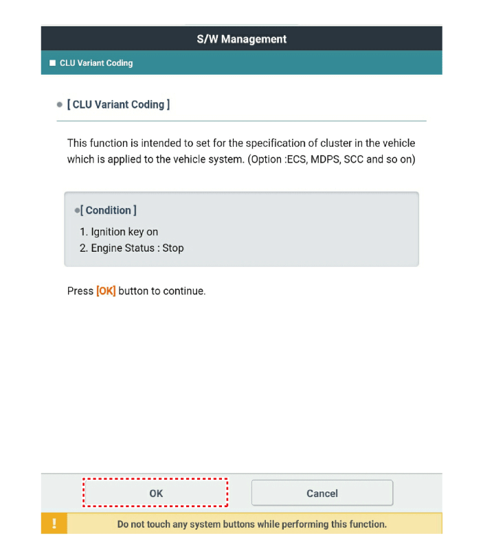
Inspection
Checkpoint (Warning Lamp)
NO Reference Symbol Name Color Input Signal Signal Control Checkpoint 1 
Turn Signal (Left) Green CAN ICU
(Gateway)1) Multifunction switch
2) ICU
3) CAN malfunction2 
Turn Signal (Right) Green CAN ICU
(Gateway)1) Multifunction switch
2) ICU
3) CAN malfunction3 
Rear Lamp Green CAN ICU
(Gateway)1) Multifunction switch
2) ICU
3) CAN malfunction4 
Front Fog Lamp Green CAN ICU
(Gateway)1) Multifunction switch
2) ICU
3) CAN malfunction5 
Rear Fog Lamp Yellow CAN ICU
(Gateway)1) Multifunction switch
2) ICU
3) CAN malfunction6 
High Beam Blue CAN ICU
(Gateway)1) Multifunction switch
2) ICU
3) CAN malfunction7 
Low Beam Green CAN ICU
(Gateway)1) Multifunction switch
2) MSB
3) CAN malfunction8 
LED Headlamp Yellow CAN AFS 1) AFS system
2) CAN malfunction9 
Warning Yellow CAN SCP 1) TPMS system
2) CAN malfunctionICU (Intensive Care Unit) 1) Exterior lamp
2) MSB
3) CAN malfunctionYellow Hard Wired Low Washer 1) Washer fluid level sensor
2) Wiring malfunctionDigital Input Service inspection reminder 10 
Battery Charge Red Hard Wired Generator 1) Alternator
2) Wiring malfunction
3) Battery11 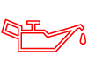
Oil Pressure Red Hard Wired ECM 1) Oil pressure sensor
2) Wiring malfunction
3) ECM
4) CAN malfunction12 
Check Engine Yellow CAN ECM 1) ECM
2) CAN malfunction13 
Immobilizer Yellow CAN IMMOBILIZER
SMK1) Immobilizer system
2) MSB
3) CAN malfunction
4) Hard wiring14 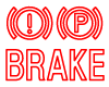
Parking Brake
Brake Fluid
EBD
EPB
Executive Vice PresidentRed CAN ICU
(Gateway)
EBD
EPB
Executive Vice President
ABS
TCS1) MSB
2) ABS system
3) EPB system
4) CAN malfunction
5) Parking brake switch
6) Brake fluid lever sensor15 
ABS Yellow CAN ABS 1) ABS system
2) CAN malfunction16 
ESC Yellow CAN TCS 1) ABS system
2) CAN malfunction17 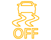
ESC OFF Yellow CAN TCS 1) ABS system
2) CAN malfunction18 
EPB Yellow CAN EPB 1) EPB system
2) CAN malfunction19 
Auto Hold White
Yellow
GreenCAN VDC 1) TCS system
2) CAN malfunction20 
Seat belt Red CAN ICU
(Gateway)1) ICU
2) CAN malfunction21 
Air Bag Red CAN SRSCM 1) SRSCM system
2) CAN malfunction22 
EPS
(MDPS)Red CAN MDPS 1) MDPS unit system
2) MDPS motor
3) CAN malfunction23 

HDA White
GreenCAN MFC 1) HDA system
2) CAN malfunction24 
SCP Yellow CAN SCP 1) TPMS system
2) TPMS sensor
3) CAN malfunction25 
LKA White
Yellow
GreenCAN LKA 1) LKA system
2) CAN malfunction26 
Fuel Warning Yellow Direct
(Micom)Fuel Sender 1) Fuel sensor malfunction
2) Wiring malfunction27 
ECO Green Hard Wired ECO Mode 1) Drive mode switch
2) ECU system
3) TCU system28 
SPORT Yellow Hard Wired SPORT Mode 1) Drive mode switch
2) ECU system
3) TCU system29 
CRUISE Green CAN ECM 1) ECM
2) CAN malfunction30

FCA Yellow CAN MFC
SCC1) MFC system
2) SCC malfunction
3) CAN malfunction31 
AUTO HOLD Green
YellowCAN ECM 1) ECU system
2) CAN malfunctionTR Switch (Sensor)
NO Name Input Signal Signal Control
(Unit/Sensor)Checkpoint 1 Speedometer C-CAN ABS/ESC 1) CAN line failure 3 Tachometer C-CAN Emergency Call 1) CAN line failure 4 Engine Coolant Temperature C-CAN Emergency Call 1) CAN line failure 5 Fuel Hard Wire Fuel Sender 1) Fuel level sensor malfunction 2) Wiring malfunction 6 Shift Lever Indicator C-CAN TCU 1) CAN line failure
Diagnosis Using KDS
In the body electrical system, faults can be quickly diagnosed using the Korean Diagnostic System (KDS).
The Diagnostic System (KDS) provides the following information.
Self-Diagnosis: Checks malfunction and Diagnostic Trouble Code (DTC)
Current Data: Check the system input/output status.
Actuation Test: Check the system operating status
Additional function: Control of other functions, including the setting parameter system and zero point adjustment.
Select "Vehicle Model" and "Cluster Module (CLU)" to inspect. Order vehicle inspection using the tester.
Select the "Current Data" menu to view the current input/output data status.
Input/output data for sensors related to the Cluster Module (CLU) can be inspected.
To forcibly activate the input value of the module under test, select the "Activation Test" option.
Troubleshooting
Troubleshooting
| Error Item | Failure Symptom | Check Items | Detailed Checks | Related Parts/ Components |
| On-Screen Display | LCD screen does not turn on |
|
|
Connectors, Wiring, Fuses, Instrument Cluster |
| Warning Light | Airbag Warning Lamp Malfunction |
|
|
ACU Connectors, Wiring, Fuses, Instrument Cluster |
| Mode Conversion | Built-in Drive Mode Malfunction |
|
|
Switch Connector, Cluster Wiring |
| Illumination | Interior Illumination Brightness Cannot Be Adjusted. |
|
|
Switch Connector, Cluster Wiring |
| Warning Sound | No Warning Chime on Instrument Cluster |
|
|
Speaker connectors, instrument panel wiring |
| Fuel Gauge | Incorrect fuel level gauge indication |
|
|
Fuel level sender connector, instrument panel wiring |
Test yourself
A quick Kia Optima DL3 quiz: every answer comes with an explanation and a link to the manual page.