Body Electrical System
eCall Module
In this manual: Body Electrical System
33steps
~198min
5/5difficulty
Done 0 of 33
Components and Component Location
Component
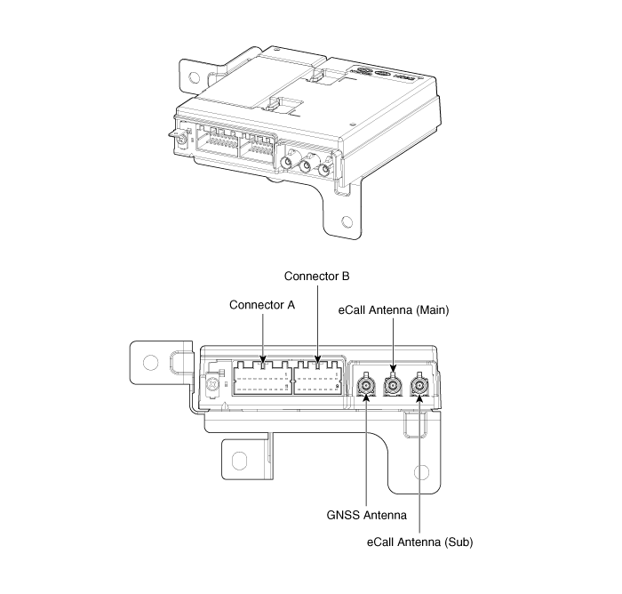
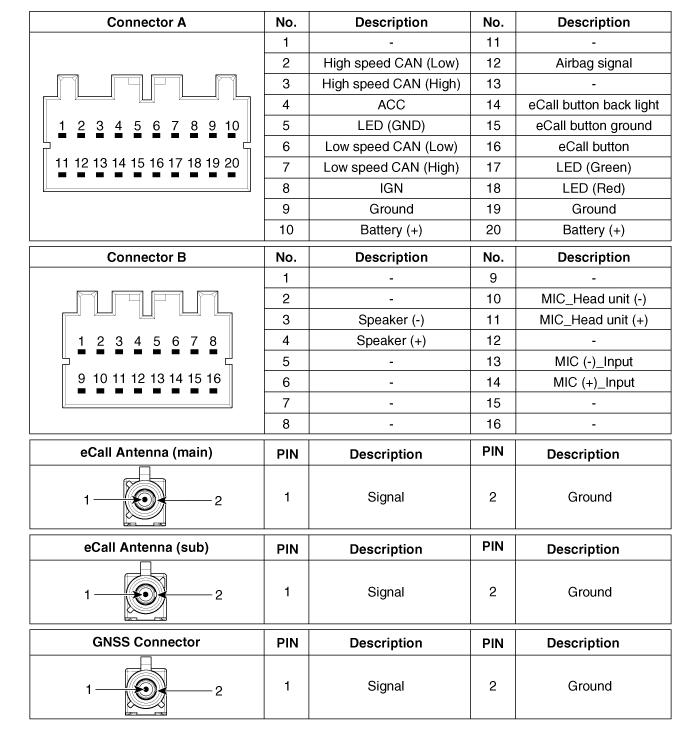
Repair Procedures
Removal
eCall module- Disconnect the negative (-) battery terminal.
- Remove the audio unit or AVN head unit. (Refer to Audio - "Audio Unit") (Refer to AVN System - "AVN Head Unit (Audio Video Navigation)").
- Disconnect the connectors from the eCall module (A).
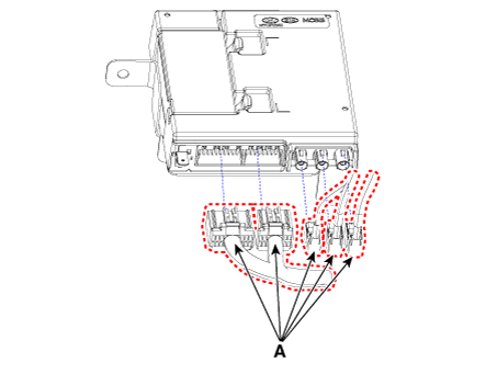
- Remove the eCall module (A) after loosening the mounting bolt and nuts.
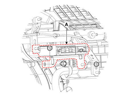
- Disconnect the negative (-) battery terminal.
- Remove the instrument cluster. (Refer to Gauges and Sensors - "Instrument Cluster")
- Disconnect the eCall antenna connector (A).
- Loosen the mounting nuts (C), then remove the eCall antenna (B).
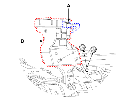
- Disconnect the negative (-) battery terminal.
- Remove the emergency pad lower panel. (Refer to Body - "Emergency Pad Lower Panel")
- Disconnect the eCall speaker connector (A).
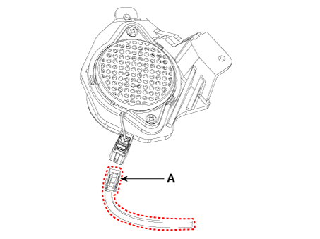
- Remove the eCall speaker (A) after loosening the mounting nuts.
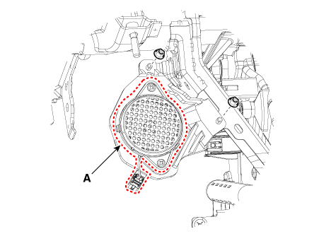
Replacement
eCall Backup Battery (BUB)- Disconnect the negative (-) battery terminal.
- Remove the eCall module.
- To replace the backup battery, remove it after removing the backup battery cover (A).
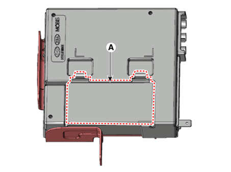
Installation
eCall module- Install the eCall module.
- Connect the connectors to the eCall module.
- Install the audio unit or AVN head unit.
- Connect the negative (-) battery terminal.
- Install the eCall antenna.
- Connect the eCall antenna connector.
- Install the instrument cluster.
- Connect the negative (-) battery terminal.
- Install the eCall speaker.
- Connect the eCall speaker connector.
- Install the emergency pad lower panel.
- Connect the negative (-) battery terminal.
Inspection
Inspection (with KDS/GDS)- Body electrical system malfunctions can be quickly diagnosed using the vehicle diagnostic system (KDS/GDS). The diagnostic system (KDS/GDS) provides the following information.
- Self-Diagnosis: Checks for malfunctions and Diagnostic Trouble Codes (DTCs).
- Current Data: Checks the input/output status of the system.
- Actuation Test: Checks the operating condition of the system.
- Additional function: Controls other functions, including system parameter setting and zero point adjustment.
- Select "Vehicle Model" and "Telematics System" to check the vehicle with the scan tool.
- Select the "Current Data" menu to check the current status of the inputs/outputs.
- Test Mode Operating Conditions
- The vehicle battery is connected properly.
- One minute has passed after ignition ON.
- The vehicle remains stationary for 1 minute or more.
- Conditions Preventing Test Mode Operation
- PSAP Call in Progress
- Callback Mode: After a successful call, the eCall system enters callback mode and stands by for 120 minutes to receive calls from the call center.
- Test mode ends automatically when vehicle speed reaches 1 km/h or above, or when the vehicle travels 300 m or more.
- Less than two minutes have passed since the previous test call was completed.
- Test Mode Sequence (Audio Guidance)
- LED Test
- Speaker Test
- MIC Test
- BUB (Backup Battery built into the eCall module) Test (no separate notification is provided if the BUB is in normal condition).
- Test Call (pressing the SOS button sends the test result to the PSAP.)
Test yourself
A quick Kia Picanto JA quiz: every answer comes with an explanation and a link to the manual page.
Was this page helpful?